TTCAN | User’s Manual | Revision 1.6 |
manual_about.fm
3.3.3.3 IFx Message Control Registers
IF1 Message Control Register | 15 | 14 | 13 | 12 | 11 | 10 | 9 | 8 | 7 | 6 5 4 | 3 2 1 0 | |
(addresses 0x1D & 0x1C) |
|
|
|
|
|
|
|
|
|
| ||
NewDat | MsgLst | IntPnd | UMask | TxIE | RxIE | RmtEn | TxRqst | EoB | ||||
|
|
|
|
|
|
|
|
|
|
|
| |
IF2 Message Control Register | NewDat | MsgLst | IntPnd | UMask | TxIE | RxIE | RmtEn | TxRqst | EoB | |||
(addresses 0x4D & 0x4C) |
|
|
|
|
|
|
|
|
|
|
| |
rw | rw | rw | rw | rw | rw | rw | rw | rw | rw | rw | ||
| ||||||||||||
|
|
|
|
|
|
|
|
|
|
|
| |
3.3.3.4 IFx Data A and Data B Registers
The data bytes of CAN messages are stored in the IFx registers in the following order:
|
| 15 | 14 | 13 | 12 | 11 | 10 | 9 | 8 | 7 | 6 | 5 | 4 | 3 | 2 | 1 | 0 |
|
|
|
|
|
|
|
|
|
|
|
|
|
|
| |||
IF1 Message Data A1 (addresses 0x1F & 0x1E) |
|
|
| Data(1) |
|
|
|
|
|
| Data(0) |
|
|
| |||
|
|
|
|
|
|
|
|
|
|
|
|
|
|
| |||
IF1 Message Data A2 (addresses 0x21 & 0x20) |
|
|
| Data(3) |
|
|
|
|
|
| Data(2) |
|
|
| |||
|
|
|
|
|
|
|
|
|
|
|
|
|
|
|
| ||
IF1 Message Data B1 (addresses 0x23 | & 0x22) |
|
|
| Data(5) |
|
|
|
|
|
| Data(4) |
|
|
| ||
|
|
|
|
|
|
|
|
|
|
|
|
|
|
|
| ||
IF1 Message Data B2 (addresses 0x25 | & 0x24) |
|
|
| Data(7) |
|
|
|
|
|
| Data(6) |
|
|
| ||
|
|
|
|
|
|
|
|
|
|
|
|
|
|
|
| ||
IF2 Message Data A1 (addresses 0x4F | & 0x4E) |
|
|
| Data(1) |
|
|
|
|
|
| Data(0) |
|
|
| ||
|
|
|
|
|
|
|
|
|
|
|
|
|
|
| |||
IF2 Message Data A2 (addresses 0x51 & 0x50) |
|
|
| Data(3) |
|
|
|
|
|
| Data(2) |
|
|
| |||
|
|
|
|
|
|
|
|
|
|
|
|
|
|
|
| ||
IF2 Message Data B1 (addresses 0x53 | & 0x52) |
|
|
| Data(5) |
|
|
|
|
|
| Data(4) |
|
|
| ||
|
|
|
|
|
|
|
|
|
|
|
|
|
|
|
| ||
IF2 Message Data B2 (addresses 0x55 | & 0x54) |
|
|
| Data(7) |
|
|
|
|
|
| Data(6) |
|
|
| ||
|
|
|
|
|
|
|
|
|
|
|
|
|
|
|
|
| |
|
|
|
|
| rw |
|
|
|
|
|
|
| rw |
|
|
| |
|
|
|
|
|
|
|
|
|
|
|
|
|
|
|
|
|
|
In a CAN Data Frame, Data(0) is the first, Data(7) is the last byte to be transmitted or received. In CAN’s serial bit stream, the MSB of each byte will be transmitted first.
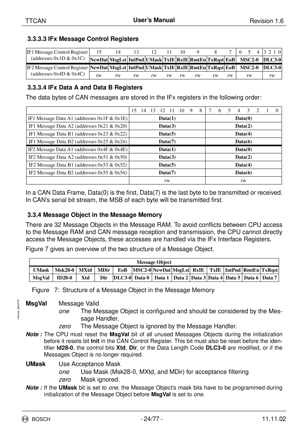
3.3.4 Message Object in the Message Memory
There are 32 Message Objects in the Message RAM. To avoid conflicts between CPU access to the Message RAM and CAN message reception and transmission, the CPU cannot directly access the Message Objects, these accesses are handled via the IFx Interface Registers.
Figure 7 gives an overview of the two structure of a Message Object.
Message Object
UMask | MXtd | MDir | EoB | NewDat | MsgLst | RxIE | TxIE | IntPnd | RmtEn | TxRqst | ||
|
|
|
|
|
|
|
|
|
|
|
|
|
MsgVal | Xtd | Dir | Data 0 | Data 1 | Data 2 | Data 3 | Data 4 | Data 5 | Data 6 | Data 7 | ||
|
|
|
|
|
|
|
|
|
|
|
|
|
Figure 7: Structure of a Message Object in the Message Memory
MsgVal Message Valid
one The Message Object is configured and should be considered by the Mes- sage Handler.
zero The Message Object is ignored by the Message Handler.
Note : The CPU must reset the MsgVal bit of all unused Messages Objects during the initialization before it resets bit Init in the CAN Control Register. This bit must also be reset before the iden- tifier
UMask Use Acceptance Mask
one Use Mask (Msk28-0, MXtd, and MDir) for acceptance filtering zero Mask ignored.
Note : If the UMask bit is set to one, the Message Object’s mask bits have to be programmed during initialization of the Message Object before MsgVal is set to one.
BOSCH | - 24/77 - | 11.11.02 |