TTCAN | User’s Manual | Revision 1.6 |
2.2 Block Diagram
manual_about.fm
|
|
|
| CAN_TX |
|
|
|
| CAN_Core |
|
|
|
| CAN_RX |
|
|
|
| |
Clock |
|
|
|
|
Reset |
|
|
| Message RAM |
Control |
| 1 | 2 | |
| (single ported) | |||
| Register | Register | ||
| Interface | |||
Address |
| |||
|
|
|
| |
DataIN | Module | CPUIFC | CPUIFC |
|
| Message Handler | |||
|
|
|
| |
DataOUT |
|
|
|
|
Wait |
|
|
| Trigger Memory |
|
|
|
| |
Interrupt |
|
|
| Trigger |
|
|
|
|
SWT, EVT
TTCAN - Frame Synchronisation Entity
TMI
TTCAN
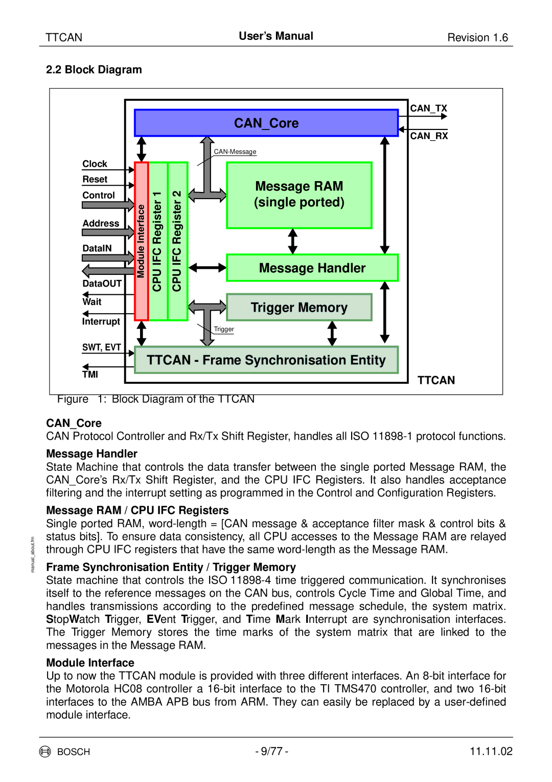
Figure 1: Block Diagram of the TTCAN
CAN_Core
CAN Protocol Controller and Rx/Tx Shift Register, handles all ISO
Message Handler
State Machine that controls the data transfer between the single ported Message RAM, the CAN_Core’s Rx/Tx Shift Register, and the CPU IFC Registers. It also handles acceptance filtering and the interrupt setting as programmed in the Control and Configuration Registers.
Message RAM / CPU IFC Registers
Single ported RAM,
Frame Synchronisation Entity / Trigger Memory
State machine that controls the ISO
Module Interface
Up to now the TTCAN module is provided with three different interfaces. An
BOSCH | - 9/77 - | 11.11.02 |
