TTCAN | User’s Manual | Revision 1.6 |
manual_about.fm
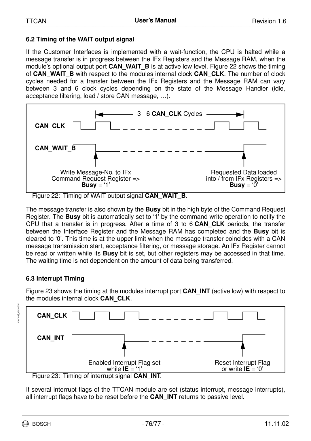
6.2 Timing of the WAIT output signal
If the Customer Interfaces is implemented with a
3 - 6 CAN_CLK Cycles
CAN_CLK |
|
|
|
|
|
|
|
|
|
|
|
|
|
|
|
|
|
|
|
|
| ||
CAN_WAIT_B |
|
|
|
|
|
|
|
|
| ||
|
| ||||||||||
|
|
|
| ||||||||
Write | Requested Data loaded | ||||||||||
Command Request Register => | into / from IFx Registers => | ||||||||||
|
| Busy = ‘1’ |
|
| Busy = ‘0’ | ||||||
|
|
|
|
|
|
| |||||
Figure 22: Timing of WAIT output signal CAN_WAIT_B. |
|
|
|
|
|
| |||||
The message transfer is also shown by the Busy bit in the high byte of the Command Request Register. The Busy bit is automatically set to ‘1’ by the command write operation to notify the CPU that a transfer is in progress. After a time of 3 to 6 CAN_CLK periods, the transfer between the Interface Register and the Message RAM has completed and the Busy bit is cleared to ‘0’. This time is at the upper limit when the message transfer coincides with a CAN message transmission start, acceptance filtering, or message storage. An IFx Register cannot be read or written while its Busy bit is set, but other registers may be accessed in that time. The waiting time is not dependent on the amount of data being transferred.
6.3 Interrupt Timing
Figure 23 shows the timing at the modules interrupt port CAN_INT (active low) with respect to the modules internal clock CAN_CLK.
CAN_CLK
CAN_INT
Enabled Interrupt Flag set | Reset Interrupt Flag |
while IE = ‘1’ | or write IE = ‘0’ |
Figure 23: Timing of interrupt signal CAN_INT. |
|
If several interrupt flags of the TTCAN module are set (status interrupt, message interrupts), all interrupt flags have to be reset before the CAN_INT returns to passive level.
BOSCH | - 76/77 - | 11.11.02 |