TTCAN | User’s Manual | Revision 1.6 |
Start of | actual Ref Mark | Sync Mark |
Basic Cycle | ||
previous RefMark |
Calibration of | ? | ⎟ |
Time Unit Ratio | = 1 |
previous Master_Ref_Mark
| Master Ref | actual | |
| Mark |
| |
|
|
|
|
|
|
|
|
|
|
|
|
|
|
|
|
Reference Message
manual_about.fm
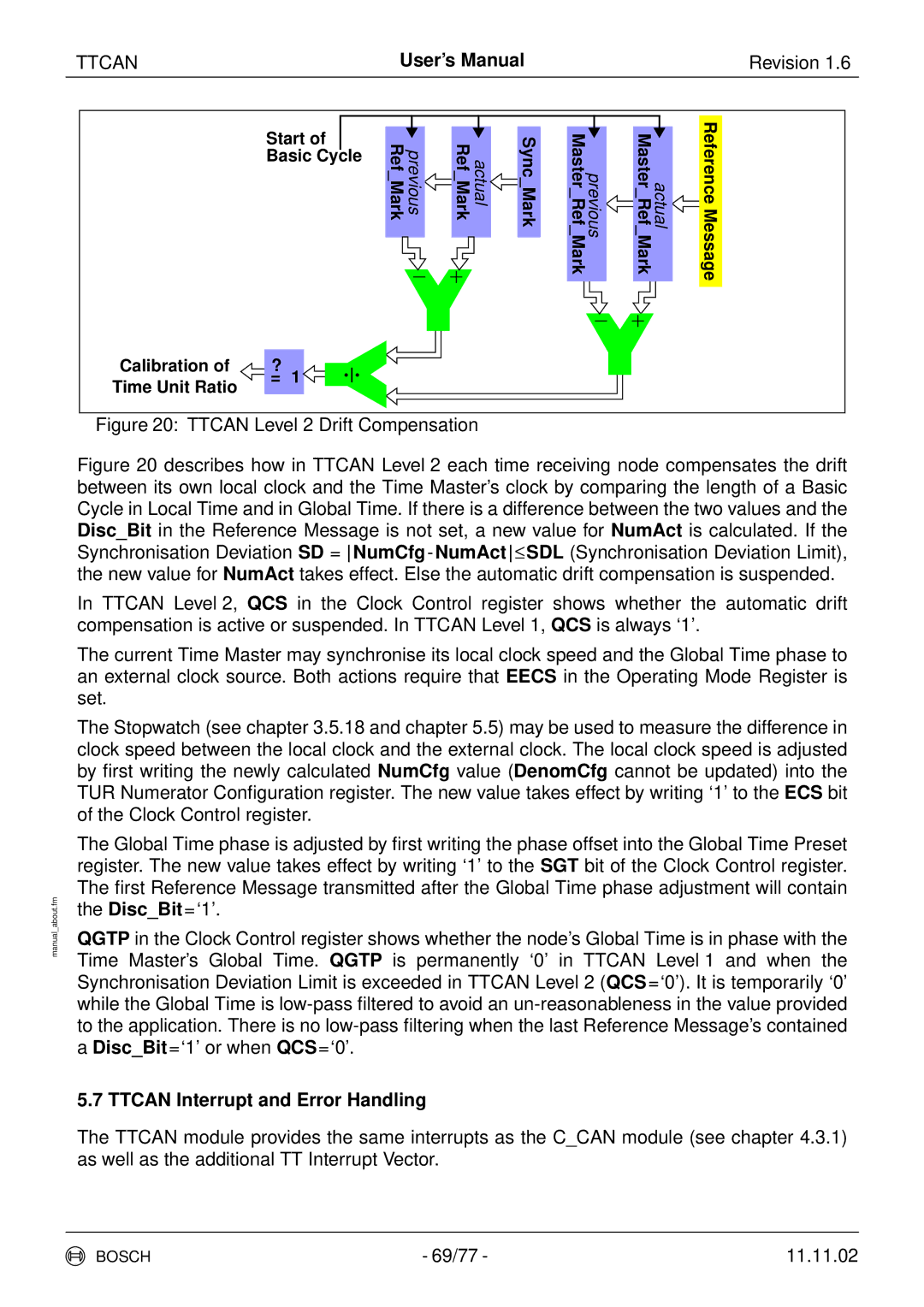
Figure 20: TTCAN Level 2 Drift Compensation
Figure 20 describes how in TTCAN Level 2 each time receiving node compensates the drift between its own local clock and the Time Master’s clock by comparing the length of a Basic Cycle in Local Time and in Global Time. If there is a difference between the two values and the Disc_Bit in the Reference Message is not set, a new value for NumAct is calculated. If the Synchronisation Deviation SD = NumCfg-NumAct≤SDL (Synchronisation Deviation Limit), the new value for NumAct takes effect. Else the automatic drift compensation is suspended.
In TTCAN Level 2, QCS in the Clock Control register shows whether the automatic drift compensation is active or suspended. In TTCAN Level 1, QCS is always ‘1’.
The current Time Master may synchronise its local clock speed and the Global Time phase to an external clock source. Both actions require that EECS in the Operating Mode Register is set.
The Stopwatch (see chapter 3.5.18 and chapter 5.5) may be used to measure the difference in clock speed between the local clock and the external clock. The local clock speed is adjusted by first writing the newly calculated NumCfg value (DenomCfg cannot be updated) into the TUR Numerator Configuration register. The new value takes effect by writing ‘1’ to the ECS bit of the Clock Control register.
The Global Time phase is adjusted by first writing the phase offset into the Global Time Preset register. The new value takes effect by writing ‘1’ to the SGT bit of the Clock Control register. The first Reference Message transmitted after the Global Time phase adjustment will contain the Disc_Bit=‘1’.
QGTP in the Clock Control register shows whether the node’s Global Time is in phase with the Time Master’s Global Time. QGTP is permanently ‘0’ in TTCAN Level 1 and when the Synchronisation Deviation Limit is exceeded in TTCAN Level 2 (QCS=‘0’). It is temporarily ‘0’ while the Global Time is low-pass filtered to avoid an un-reasonableness in the value provided to the application. There is no low-pass filtering when the last Reference Message’s contained a Disc_Bit=‘1’ or when QCS=‘0’.
5.7 TTCAN Interrupt and Error Handling
The TTCAN module provides the same interrupts as the C_CAN module (see chapter 4.3.1) as well as the additional TT Interrupt Vector.
BOSCH | - 69/77 - | 11.11.02 |