TTCAN | User’s Manual | Revision 1.6 |
manual_about.fm
6. CPU Interface
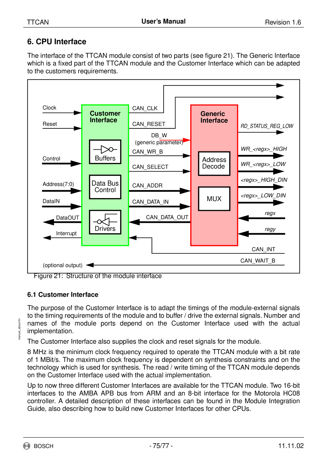
The interface of the TTCAN module consist of two parts (see figure 21). The Generic Interface which is a fixed part of the TTCAN module and the Customer Interface which can be adapted to the customers requirements.
Clock | Customer | CAN_CLK | Generic |
|
|
|
| ||
Reset | Interface | CAN_RESET | Interface | RD_STATUS_REG_LOW |
|
| |||
|
|
|
| |
|
| DB_W |
|
|
|
| (generic parameter) |
|
|
|
| CAN_WR_B |
| WR_<regx>_HIGH |
| Buffers |
|
| |
Control |
| Address | WR_<regx>_LOW | |
|
| CAN_SELECT | Decode | |
Address(7:0) | Data Bus | CAN_ADDR |
| <regx>_HIGH_DIN |
|
| |||
| Control |
|
| <regx>_LOW_DIN |
DataIN |
| CAN_DATA_IN | MUX | |
|
| |||
|
|
| ||
DataOUT |
| CAN_DATA_OUT |
| regx |
|
|
| ||
Interrupt | Drivers |
|
| regy |
|
|
|
| |
|
|
|
| CAN_INT |
(optional output) |
|
|
| CAN_WAIT_B |
|
|
|
| |
Figure 21: Structure of the module interface |
|
| ||
6.1 Customer Interface
The purpose of the Customer Interface is to adapt the timings of the
The Customer Interface also supplies the clock and reset signals for the module.
8 MHz is the minimum clock frequency required to operate the TTCAN module with a bit rate of 1 MBit/s. The maximum clock frequency is dependent on synthesis constraints and on the technology which is used for synthesis. The read / write timing of the TTCAN module depends on the Customer Interface used with the actual implementation.
Up to now three different Customer Interfaces are available for the TTCAN module. Two
BOSCH | - 75/77 - | 11.11.02 |
