TTCAN | User’s Manual | Revision 1.6 |
manual_about.fm
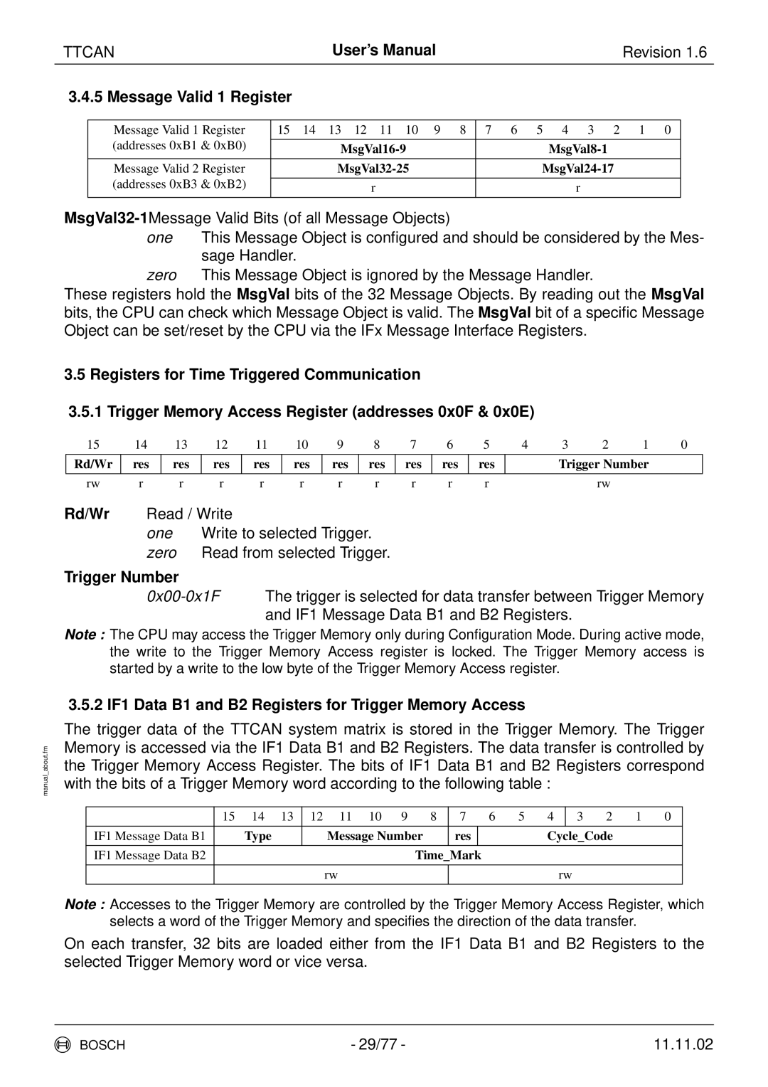
3.4.5 Message Valid 1 Register
Message Valid 1 Register | 15 14 13 12 11 10 9 8 | 7 | 6 5 4 3 2 1 0 |
(addresses 0xB1 & 0xB0) |
|
|
|
| |||
|
|
|
|
Message Valid 2 Register |
| ||
(addresses 0xB3 & 0xB2) |
|
|
|
r |
| r | |
|
| ||
|
|
|
|
one This Message Object is configured and should be considered by the Mes- sage Handler.
zero This Message Object is ignored by the Message Handler.
These registers hold the MsgVal bits of the 32 Message Objects. By reading out the MsgVal bits, the CPU can check which Message Object is valid. The MsgVal bit of a specific Message Object can be set/reset by the CPU via the IFx Message Interface Registers.
3.5Registers for Time Triggered Communication
3.5.1Trigger Memory Access Register (addresses 0x0F & 0x0E)
15 | 14 | 13 | 12 | 11 | 10 | 9 | 8 | 7 | 6 | 5 | 4 | 3 | 2 | 1 | 0 |
Rd/Wr | res | res | res | res | res | res | res | res | res | res |
| Trigger Number |
| ||
|
|
|
|
|
|
|
|
|
|
|
|
|
|
|
|
rw | r | r | r | r | r | r | r | r | r | r |
|
| rw |
|
|
Rd/Wr Read / Write
one Write to selected Trigger. zero Read from selected Trigger.
Trigger Number
Note : The CPU may access the Trigger Memory only during Configuration Mode. During active mode, the write to the Trigger Memory Access register is locked. The Trigger Memory access is started by a write to the low byte of the Trigger Memory Access register.
3.5.2 IF1 Data B1 and B2 Registers for Trigger Memory Access
The trigger data of the TTCAN system matrix is stored in the Trigger Memory. The Trigger Memory is accessed via the IF1 Data B1 and B2 Registers. The data transfer is controlled by the Trigger Memory Access Register. The bits of IF1 Data B1 and B2 Registers correspond with the bits of a Trigger Memory word according to the following table :
| 15 | 14 | 13 | 12 | 11 | 10 | 9 | 8 | 7 |
| 6 | 5 | 4 |
| 3 | 2 | 1 | 0 |
|
|
|
|
|
|
|
|
|
|
|
|
| ||||||
IF1 Message Data B1 |
| Type |
|
| Message Number | res |
|
|
| Cycle_Code |
|
| ||||||
|
|
|
|
|
|
|
|
|
|
|
|
|
|
|
|
|
|
|
IF1 Message Data B2 |
|
|
|
|
|
|
| Time_Mark |
|
|
|
|
|
|
|
| ||
|
|
|
|
|
|
|
|
|
|
|
|
|
|
|
|
|
|
|
|
|
|
|
| rw |
|
|
|
|
|
|
|
| rw |
|
|
| |
|
|
|
|
|
|
|
|
|
|
|
|
|
|
|
|
|
|
|
Note : Accesses to the Trigger Memory are controlled by the Trigger Memory Access Register, which selects a word of the Trigger Memory and specifies the direction of the data transfer.
On each transfer, 32 bits are loaded either from the IF1 Data B1 and B2 Registers to the selected Trigger Memory word or vice versa.
BOSCH | - 29/77 - | 11.11.02 |