TTCAN | User’s Manual | Revision 1.6 |
manual_about.fm
The LEC field holds a code which indicates the type of the last error to occur on the CAN bus. This field will be cleared to ‘0’ when a message has been transferred (reception or transmis- sion) without error. The unused code ‘7’ may be written by the CPU to check for updates.
3.2.2.1 Status Interrupts
A Status Interrupt is generated by bits BOff and EWarn (Error Interrupt, EIE) or by RxOk, TxOk, and LEC (Status Change Interrupt, SIE) assumed that the corresponding enable bits in the CAN Control Register are set. A change of bit EPass or a CPU write to RxOk, TxOk, or LEC will never generate a Status Interrupt.
When SIE is set, a Status Interrupt will be generated at each CAN bus error and at each valid CAN message, independent of the Message RAM configuration.
Reading the Status Register will clear the Status Interrupt value (8000h) in the Interrupt Register, if it is pending.
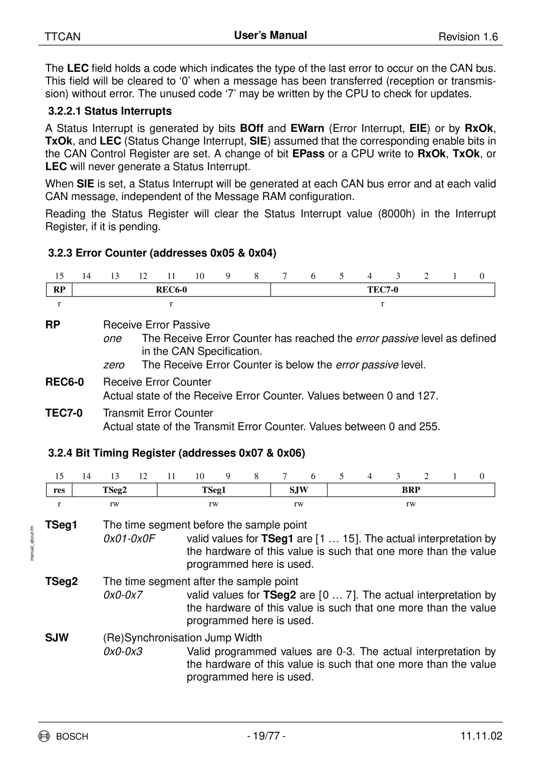
3.2.3 Error Counter (addresses 0x05 & 0x04)
15 | 14 | 13 | 12 | 11 | 10 | 9 | 8 | 7 | 6 | 5 | 4 | 3 | 2 | 1 | 0 | |
| RP |
|
|
|
|
|
|
|
|
|
|
|
| |||
|
|
|
|
|
|
|
|
|
|
|
|
|
|
|
|
|
| r |
|
|
| r |
|
|
|
|
|
|
| r |
|
|
|
RP |
| Receive Error Passive |
|
|
|
|
|
|
|
|
|
| ||||
|
|
| one | The Receive Error Counter has reached the error passive level as defined | ||||||||||||
|
|
|
| in the CAN Specification. |
|
|
|
|
|
|
|
| ||||
|
|
| zero | The Receive Error Counter is below the error passive level. |
|
| ||||||||||
Actual state of the Receive Error Counter. Values between 0 and 127.
Actual state of the Transmit Error Counter. Values between 0 and 255.
3.2.4 Bit Timing Register (addresses 0x07 & 0x06)
15 | 14 | 13 | 12 | 11 | 10 | 9 | 8 | 7 | 6 | 5 | 4 | 3 | 2 | 1 | 0 |
res |
| TSeg2 |
|
| TSeg1 |
|
| SJW |
|
|
| BRP |
|
| |
|
|
|
|
|
|
|
|
|
|
|
|
|
|
|
|
r |
| rw |
|
|
| rw |
|
| rw |
|
|
| rw |
|
|
TSeg1 The time segment before the sample point
TSeg2 The time segment after the sample point
SJW (Re)Synchronisation Jump Width
BOSCH | - 19/77 - | 11.11.02 |
