TTCAN | User’s Manual | Revision 1.6 |
BRP Baud Rate Prescaler
This register is only writable if bits CCE and Init in the CAN Control Register are set. The CAN bit time may be programed in the range of [4 … 25] time quanta. The CAN time quantum may be programmed in the range of [1 … 1024] CAN_CLK periods. For details see chapter 4.2.1.
Note : With a module clock CAN_CLK of 8 MHz and BRPE = 0x00, the reset value of 0x2301 config- ures the TTCAN for a bit rate of 500 kBit/s.
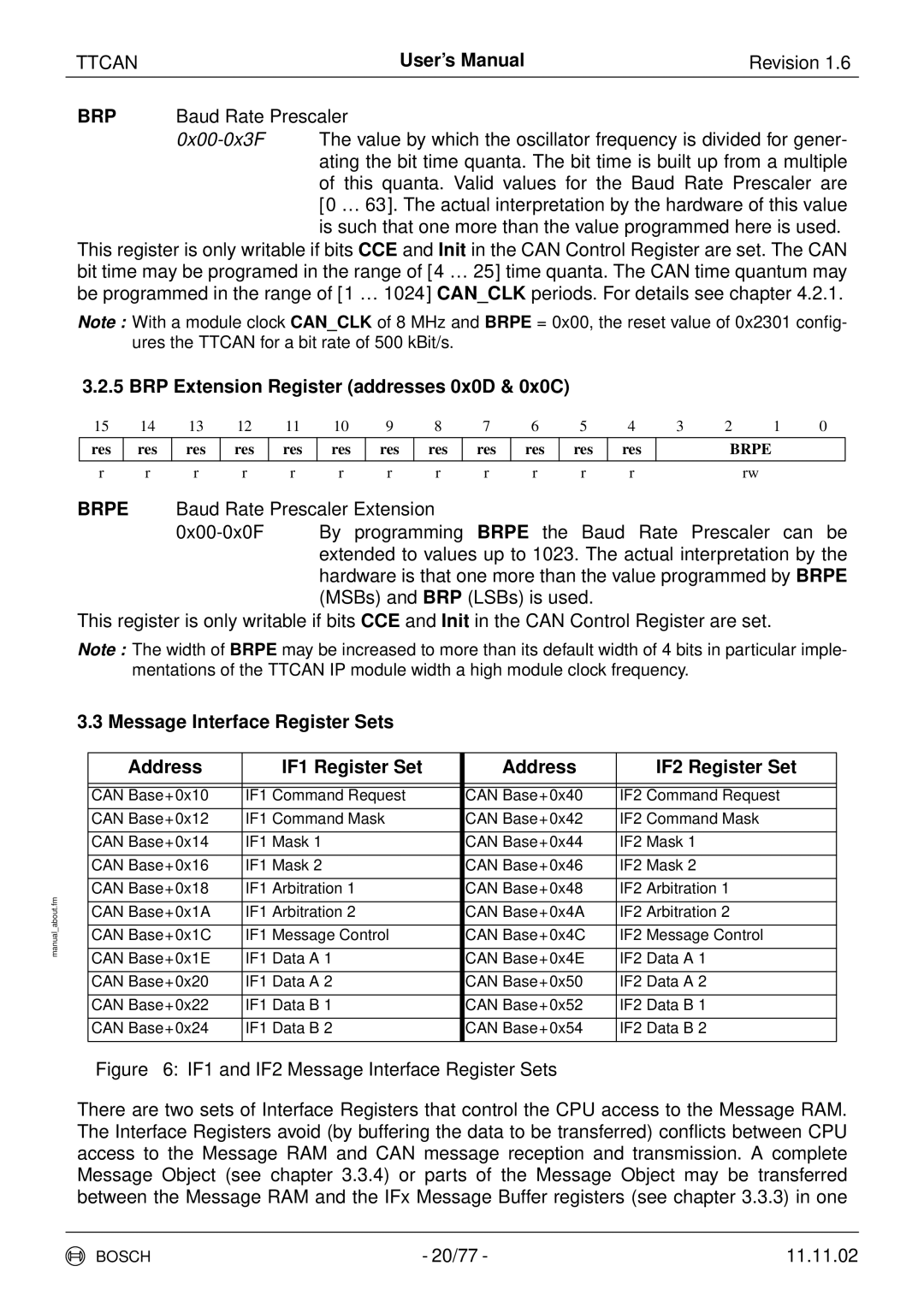
3.2.5 BRP Extension Register (addresses 0x0D & 0x0C)
15 | 14 | 13 | 12 | 11 | 10 | 9 | 8 | 7 | 6 | 5 | 4 | 3 | 2 | 1 | 0 |
res
res
res
res
res
res
res
res
res
res
res
res
BRPE
r | r | r | r | r | r | r | r | r | r | r | r | rw |
BRPE Baud Rate Prescaler Extension
This register is only writable if bits CCE and Init in the CAN Control Register are set.
Note : The width of BRPE may be increased to more than its default width of 4 bits in particular imple- mentations of the TTCAN IP module width a high module clock frequency.
| 3.3 Message Interface Register Sets |
|
| ||
|
|
|
|
|
|
|
| Address | IF1 Register Set | Address | IF2 Register Set |
|
|
|
|
|
|
|
|
|
|
|
|
|
| CAN Base+0x10 | IF1 Command Request | CAN Base+0x40 | IF2 Command Request |
|
|
|
|
|
|
|
| CAN Base+0x12 | IF1 Command Mask | CAN Base+0x42 | IF2 Command Mask |
|
|
|
|
|
|
|
| CAN Base+0x14 | IF1 Mask 1 | CAN Base+0x44 | IF2 Mask 1 |
|
|
|
|
|
|
|
| CAN Base+0x16 | IF1 Mask 2 | CAN Base+0x46 | IF2 Mask 2 |
|
|
|
|
|
|
about.fm |
| CAN Base+0x18 | IF1 Arbitration 1 | CAN Base+0x48 | IF2 Arbitration 1 |
|
|
|
|
| |
| CAN Base+0x1A | IF1 Arbitration 2 | CAN Base+0x4A | IF2 Arbitration 2 | |
|
| ||||
|
|
|
|
|
|
manual |
| CAN Base+0x1C | IF1 Message Control | CAN Base+0x4C | IF2 Message Control |
|
|
|
|
| |
| CAN Base+0x1E | IF1 Data A 1 | CAN Base+0x4E | IF2 Data A 1 | |
|
| ||||
|
|
|
|
|
|
|
| CAN Base+0x20 | IF1 Data A 2 | CAN Base+0x50 | IF2 Data A 2 |
|
|
|
|
|
|
|
| CAN Base+0x22 | IF1 Data B 1 | CAN Base+0x52 | IF2 Data B 1 |
|
|
|
|
|
|
|
| CAN Base+0x24 | IF1 Data B 2 | CAN Base+0x54 | IF2 Data B 2 |
|
|
|
|
|
|
Figure 6: IF1 and IF2 Message Interface Register Sets
There are two sets of Interface Registers that control the CPU access to the Message RAM. The Interface Registers avoid (by buffering the data to be transferred) conflicts between CPU access to the Message RAM and CAN message reception and transmission. A complete Message Object (see chapter 3.3.4) or parts of the Message Object may be transferred between the Message RAM and the IFx Message Buffer registers (see chapter 3.3.3) in one
BOSCH | - 20/77 - | 11.11.02 |