Appendix C Cable and Port Specifications
MGMT 10/100 Ethernet Port
Send documentation comments to mdsfeedback-doc@cisco.com.
Table
Note The
Table
Pin | Signal |
|
|
1 | TD+ |
|
|
2 | TD- |
|
|
3 | RD+ |
|
|
6 | RD– |
|
|
4 | Not used |
|
|
5 | Not used |
|
|
7 | Not used |
|
|
8 | Not used |
|
|
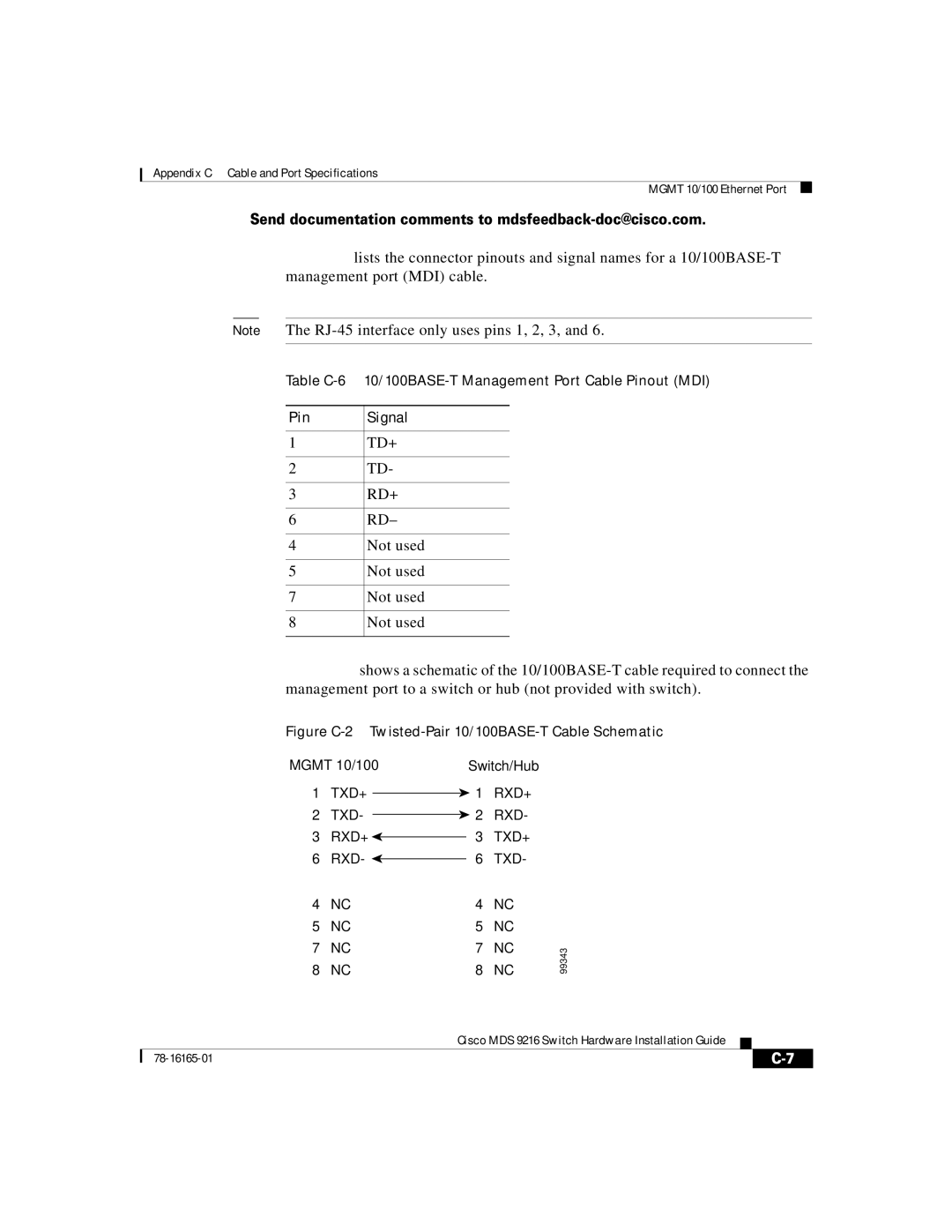
Figure C-2 shows a schematic of the 10/100BASE-T cable required to connect the management port to a switch or hub (not provided with switch).
Figure C-2 Twisted-Pair 10/100BASE-T Cable Schematic
MGMT 10/100 | Switch/Hub |
1TXD+  1 RXD+
2TXD-  2 RXD-
3RXD+  3 TXD+
6RXD-  6 TXD-
4 | NC | 4 | NC |
5 | NC | 5 | NC |
7 | NC | 7 | NC |
8 | NC | 8 | NC |
99343
|
| Cisco MDS 9216 Switch Hardware Installation Guide |
|
|
|
|
| ||
|
|
| ||
|
|
|