Chapter 2 Installing the Cisco MDS 9216 Switch
Removing and Installing Components
Send documentation comments to mdsfeedback-doc@cisco.com.
Installing a Power Supply
To install a power supply, follow these steps:
Step 1 Ensure that the system (earth) ground connection has been made. For ground connection instructions, see the “Grounding the Chassis” section on page
Step 2 If the power supply bay has a filler panel, loosen the screws holding the panel and remove the panel.
Step 3 Verify that the power switch is in the off (0) position on the power supply you are installing. See Figure
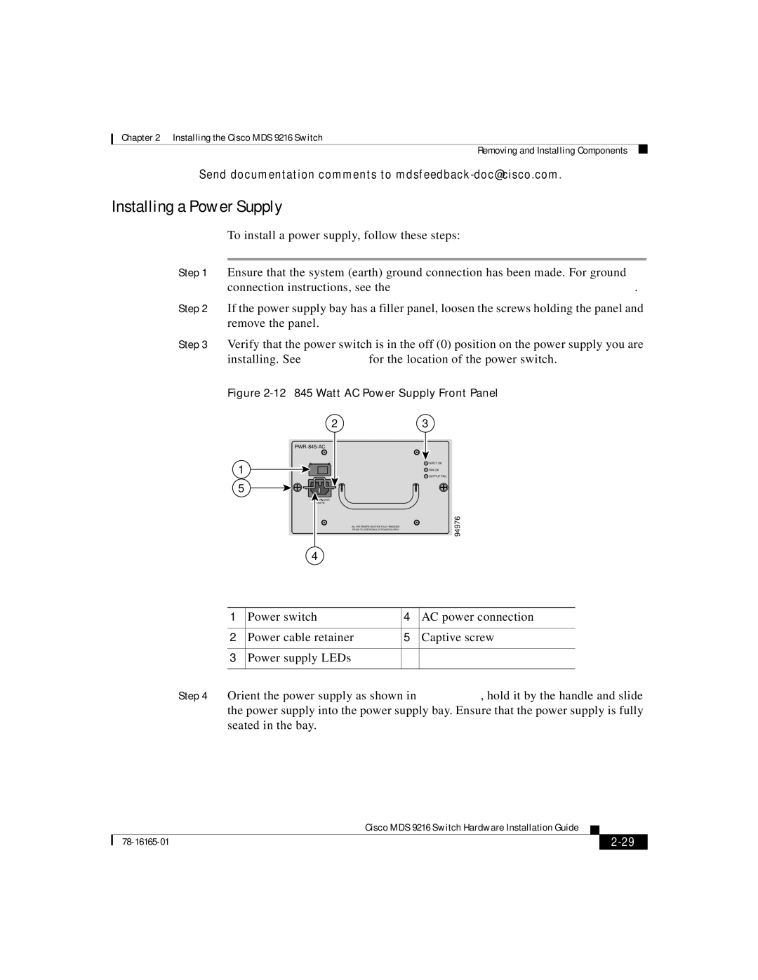
Figure 2-12 845 Watt AC Power Supply Front Panel
23
1
5
![]() 12-5A
12-5A
50/60 Hz
4
ALL FASTENERS MUST BE FULLY ENGAGED PRIOR TO OPERATING OF POWER SUPPLY
![]() INPUT OK
INPUT OK
![]() FAN OK
FAN OK
![]() OUTPUT FAIL
OUTPUT FAIL
94976
1 | Power switch | 4 | AC power connection |
|
|
|
|
2 | Power cable retainer | 5 | Captive screw |
|
|
|
|
3 | Power supply LEDs |
|
|
|
|
|
|
Step 4 Orient the power supply as shown in Figure
|
| Cisco MDS 9216 Switch Hardware Installation Guide |
|
|
|
|
| ||
|
|
| ||
|
|
|