Chapter 1 Product Overview
Switching Modules
Send documentation comments to mdsfeedback-doc@cisco.com.
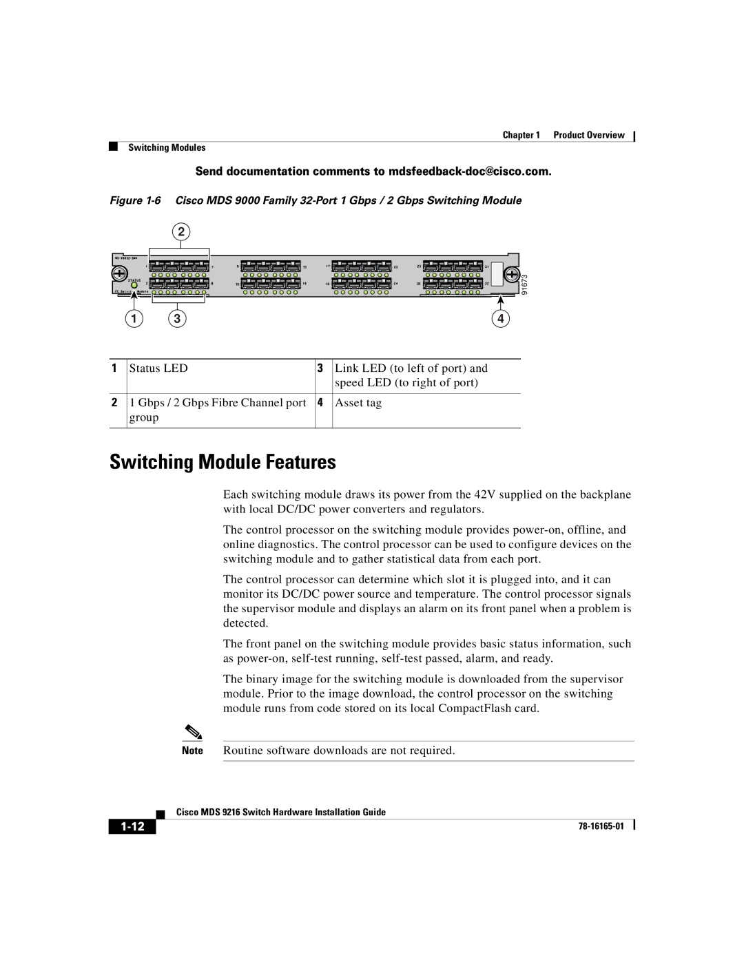
Figure 1-6 Cisco MDS 9000 Family 32-Port 1 Gbps / 2 Gbps Switching Module
2
7 |
2 |
15 |
10 |
23 |
18 |
31 |
26 | 91673 |
| 1 | 3 |
|
|
|
|
| 4 | |||
|
|
|
|
| |
1 | Status LED | 3 | Link LED (to left of port) and | ||
|
|
|
| speed LED (to right of port) | |
|
|
|
|
| |
2 | 1 Gbps / 2 Gbps Fibre Channel port | 4 | Asset tag | ||
| group |
|
|
|
|
|
|
|
|
|
|
Switching Module Features
Each switching module draws its power from the 42V supplied on the backplane with local DC/DC power converters and regulators.
The control processor on the switching module provides
The control processor can determine which slot it is plugged into, and it can monitor its DC/DC power source and temperature. The control processor signals the supervisor module and displays an alarm on its front panel when a problem is detected.
The front panel on the switching module provides basic status information, such as
The binary image for the switching module is downloaded from the supervisor module. Prior to the image download, the control processor on the switching module runs from code stored on its local CompactFlash card.
Note Routine software downloads are not required.
| Cisco MDS 9216 Switch Hardware Installation Guide |