Chapter 2 Installing the Cisco MDS 9216 Switch
Removing and Installing Components
Send documentation comments to mdsfeedback-doc@cisco.com.
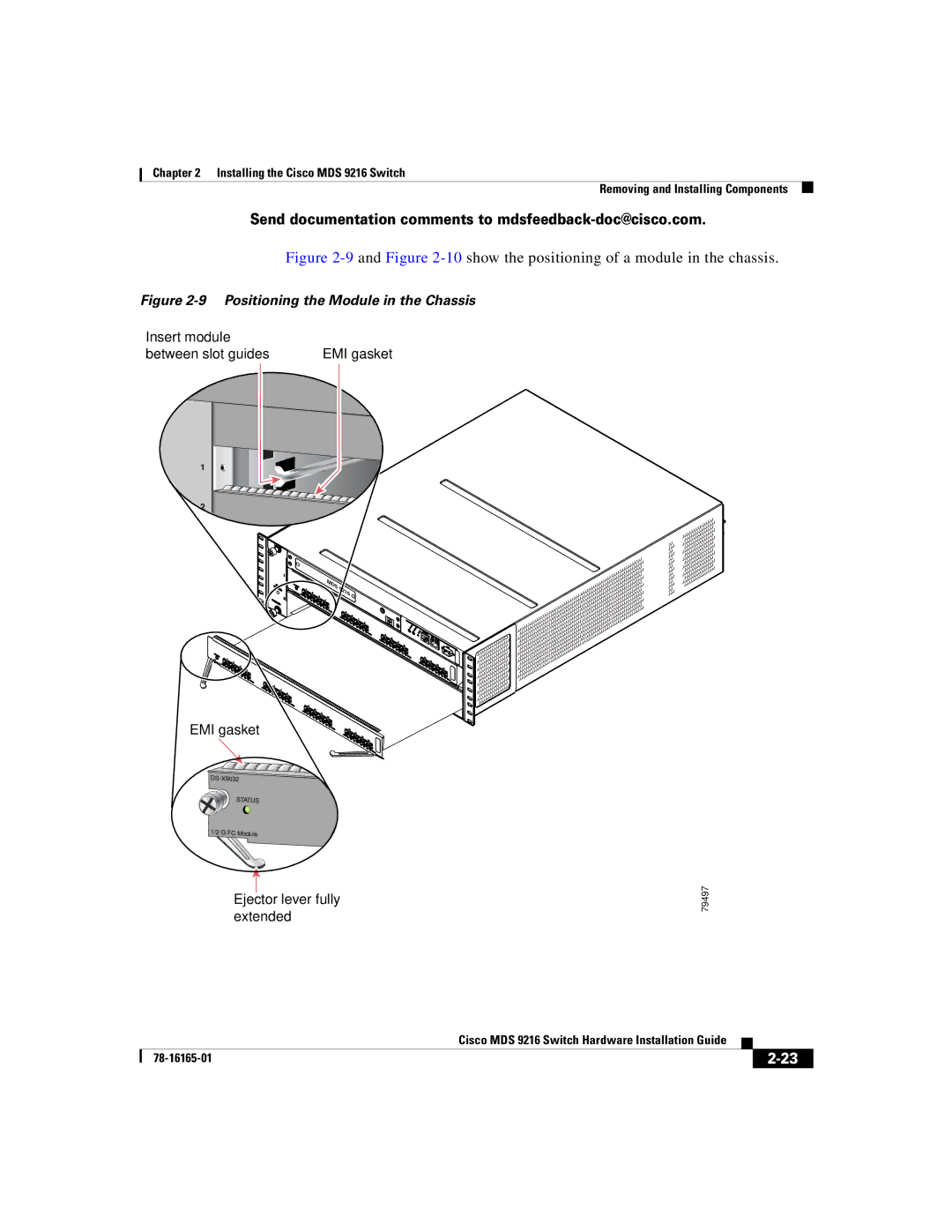
Figure 2-9 and Figure 2-10 show the positioning of a module in the chassis.
Figure 2-9 Positioning the Module in the Chassis
Insert module |
|
| |
between slot guides | EMI gasket | ||
| 3 |
|
|
| 4 |
|
|
1 |
|
|
|
2 | 6 |
|
|
|
|
| |
|
| M |
|
|
| DS | 9216 |
|
|
| |
EMI gasket
STATUS
1/2 G FC Module
Ejector lever fully extended
79497
|
| Cisco MDS 9216 Switch Hardware Installation Guide |
|
|
|
|
| ||
|
|
| ||
|
|
|