Chapter 1 Cisco XR 12404 Router Overview
|
|
| Power Entry Modules |
|
Table | ||||
|
|
|
|
|
LED Label |
| Color | Function | |
|
|
|
|
|
Input OK |
| Green | The AC power source is present and operating | |
|
|
| within the specified limit. | |
|
|
|
|
|
Output Fail |
| Amber | Indicates a failure in the PEM. | |
|
|
|
|
|
DC PEMs
Each DC PEM operates from a nominal source DC voltage of
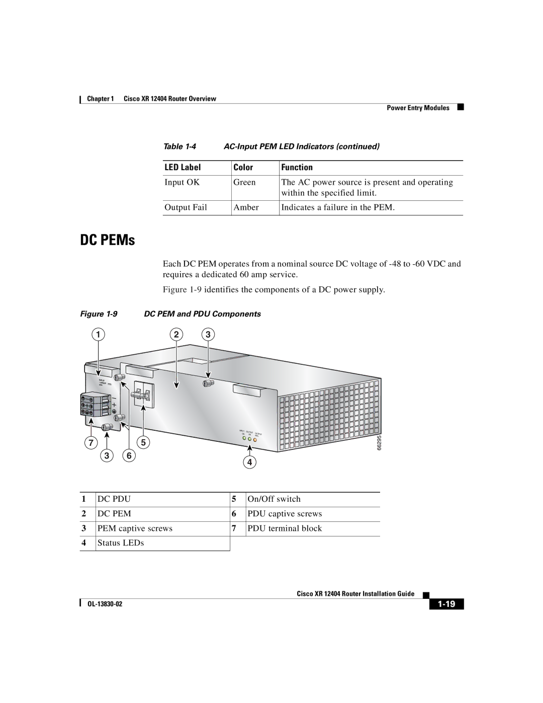
Figure 1-9 identifies the components of a DC power supply.
Figure 1-9 DC PEM and PDU Components
1 | 2 | 3 |
INPUT
–48/60V
35A
INPUT | OUTPUT | OU |
| |
OK | TPUT | |||
OK |
| |||
|
| FAIL | ||
7 | 5 |
3 6
4
66295
1 | DC PDU | 5 | On/Off switch |
|
|
|
|
2 | DC PEM | 6 | PDU captive screws |
|
|
|
|
3 | PEM captive screws | 7 | PDU terminal block |
|
|
|
|
4Status LEDs
|
| Cisco XR 12404 Router Installation Guide |
|
|
|
|
| ||
|
|
| ||
|
|
|