Chapter 3 Installing the Router
Supplemental Bonding and Grounding Connections
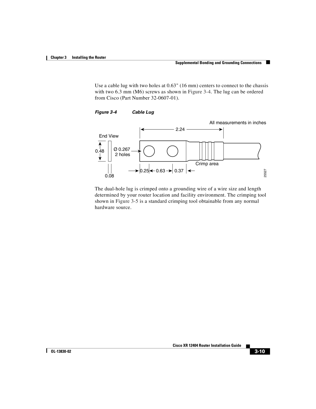
Use a cable lug with two holes at 0.63" (16 mm) centers to connect to the chassis with two 6.3 mm (M6) screws as shown in Figure
Figure | Cable Lug |
2.24
End View
|
|
|
|
| Ø 0.267 |
|
|
|
|
| |
0.48 |
| ||||
|
| 2 holes | |||
|
|
|
|
| |
|
|
|
|
|
|
![]()
![]()
![]()
![]() 0.25
0.25![]()
![]() 0.63
0.63 ![]()
![]() 0.37 0.08
0.37 0.08
All measurements in inches
Crimp area
25527
The
|
| Cisco XR 12404 Router Installation Guide |
|
|
|
|
| ||
|
|
| ||
|
|
|