Chapter 3 Installing the Router
Connecting the PRP to an Ethernet Network
Figure 3-10 Using the Ethernet Port on the PRP
Network 1.0.0.0 |
|
Router A |
|
(Cisco 12000 series) |
|
Host A |
|
EO |
|
POS |
|
Host B |
|
| Network 2.0.0.0 |
EO | Host A |
Router B |
|
(Cisco 7500 series) | S6755 |
(Cisco 7500 series) | |
Router C |
|
PRP Ethernet Connections
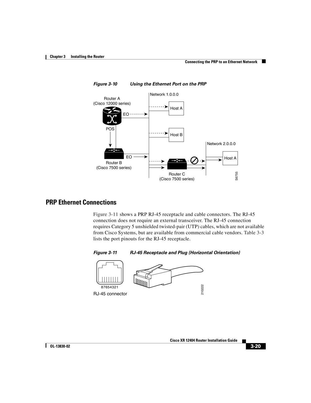
Figure 3-11 shows a PRP RJ-45 receptacle and cable connectors. The RJ-45 connection does not require an external transceiver. The RJ-45 connection requires Category 5 unshielded twisted-pair (UTP) cables, which are not available from Cisco Systems, but are available from commercial cable vendors. Table 3-3 lists the port pinouts for the RJ-45 receptacle.
Figure 3-11 RJ-45 Receptacle and Plug (Horizontal Orientation)
87654321
RJ-45 connector
210222
|
| Cisco XR 12404 Router Installation Guide |
|
|
|
|
| ||
|
|
| ||
|
|
|