Chapter 4 Troubleshooting the Installation
Troubleshooting the DC Power Subsystem
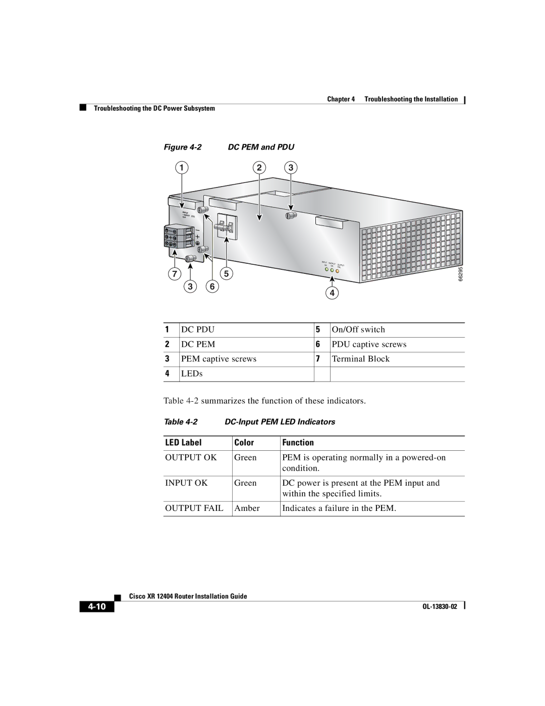
Figure 4-2 DC PEM and PDU
1 | 2 | 3 |
INPUT
–48/60V
35A
INPUT | OUTPUT | OU |
| |
OK | TPUT | |||
OK |
| |||
|
| FAIL | ||
7 | 5 |
3 6
4
66295
1 | DC PDU | 5 | On/Off switch |
2 | DC PEM | 6 | PDU captive screws |
|
|
|
|
3 | PEM captive screws | 7 | Terminal Block |
4LEDs
Table
Table | |||
|
|
|
|
LED Label |
| Color | Function |
|
|
|
|
OUTPUT OK |
| Green | PEM is operating normally in a |
|
|
| condition. |
|
|
|
|
INPUT OK |
| Green | DC power is present at the PEM input and |
|
|
| within the specified limits. |
|
|
|
|
OUTPUT FAIL |
| Amber | Indicates a failure in the PEM. |
|
|
|
|
| Cisco XR 12404 Router Installation Guide |
|