Chapter 1 Cisco XR 12404 Router Overview
Fan Tray Assembly
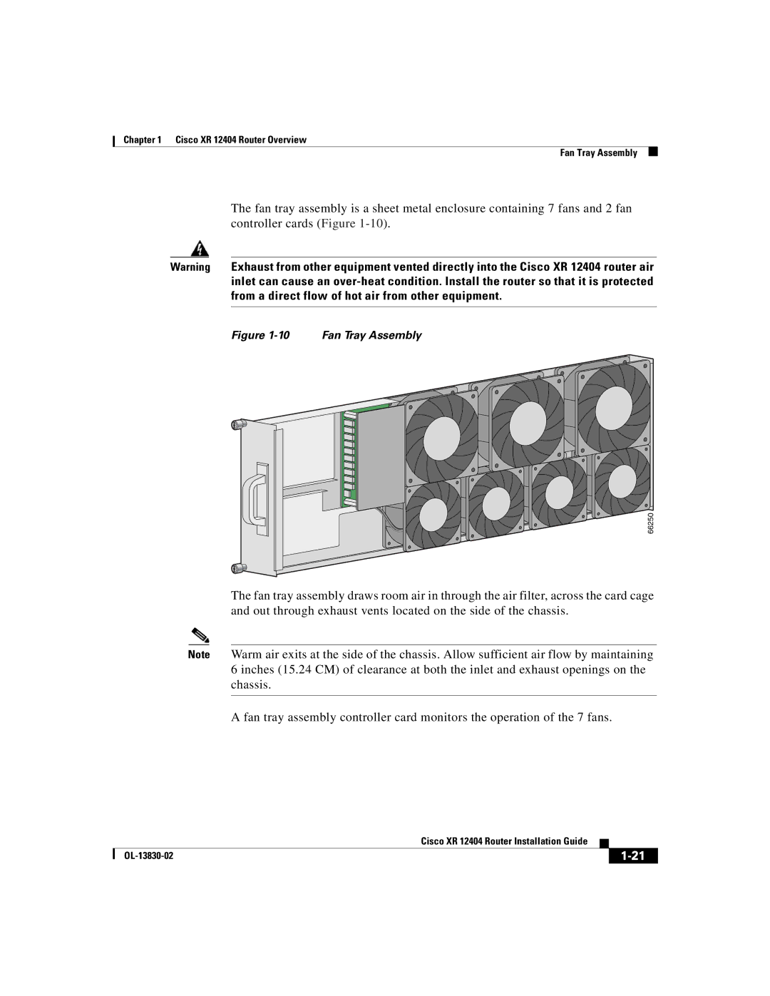
The fan tray assembly is a sheet metal enclosure containing 7 fans and 2 fan controller cards (Figure
Warning Exhaust from other equipment vented directly into the Cisco XR 12404 router air inlet can cause an
Figure 1-10 Fan Tray Assembly
66250
The fan tray assembly draws room air in through the air filter, across the card cage and out through exhaust vents located on the side of the chassis.
Note Warm air exits at the side of the chassis. Allow sufficient air flow by maintaining 6 inches (15.24 CM) of clearance at both the inlet and exhaust openings on the chassis.
A fan tray assembly controller card monitors the operation of the 7 fans.
|
| Cisco XR 12404 Router Installation Guide |
|
|
|
|
| ||
|
|
| ||
|
|
|