Chapter 4 Troubleshooting the Installation
Troubleshooting an AC Power Subsystem
Troubleshooting an AC Power Subsystem
AC PEMs provide
AC PEMs are monitored by the MBus module and the RP for over- or undervoltage and over- or undercurrent conditions.
Begin checking the power subsystem by first looking at the LEDs on the power supply. The INPUT OK LED on an AC PEM lights when AC power is applied; the OUTPUT OK LED lights when the PEM power switch is turned on.
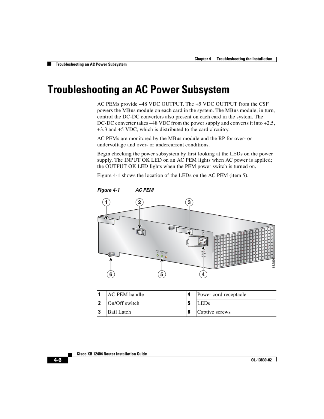
Figure 4-1 shows the location of the LEDs on the AC PEM (item 5).
Figure | AC PEM |
|
1 | 2 | 3 |
INPUT | OUTPUT OUTP |
| ||
OK | UT | |||
OK |
| |||
|
| FAIL | ||
65
INPUT
50/80HZ
66289
4
1 | AC PEM handle | 4 | Power cord receptacle |
|
|
|
|
2 | On/Off switch | 5 | LEDs |
|
|
|
|
3 | Bail Latch | 6 | Captive screws |
|
|
|
|
| Cisco XR 12404 Router Installation Guide |
|