Chapter 3 Installing the Router
Connecting to a DC Power Source
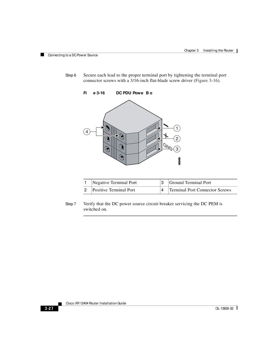
Step 6 Secure each lead to the proper terminal port by tightening the terminal port connector screws with a
Figure 3-16 DC PDU Power Block
4
![]()

![]()
![]()
![]() +
+ ![]()
![]()
![]() GND
GND
1
2
3
|
|
| 66949 |
1 | Negative Terminal Port | 3 | Ground Terminal Port |
2 | Positive Terminal Port | 4 | Terminal Port Connector Screws |
Step 7 Verify that the DC power source circuit breaker servicing the DC PEM is switched on.
| Cisco XR 12404 Router Installation Guide |
|