Chapter 3 Installing the Router
Supplemental Bonding and Grounding Connections
•On Cisco XR 12404 Routers configured for
Note Cisco XR 12404 Router grounding architecture conforms to the
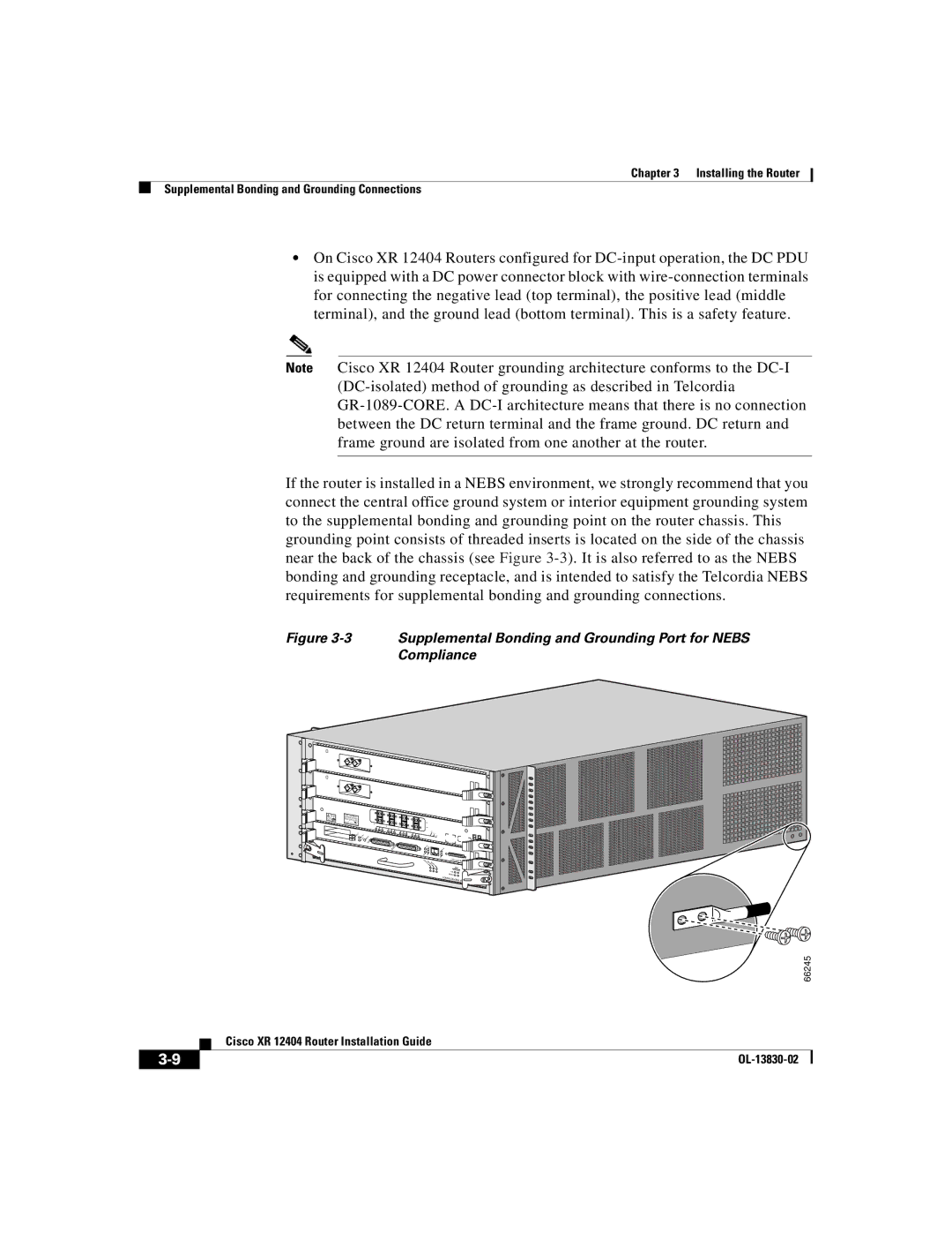
If the router is installed in a NEBS environment, we strongly recommend that you connect the central office ground system or interior equipment grounding system to the supplemental bonding and grounding point on the router chassis. This grounding point consists of threaded inserts is located on the side of the chassis near the back of the chassis (see Figure
Figure 3-3 Supplemental Bonding and Grounding Port for NEBS
Compliance
 CLEAN
CLEAN
CLASS 1 LASER | PRODUCT |
| |
LASERPRODUKT | 1 | ||
PRODUIT |
| DER KLASSE | |
| LASER DE CLASSE | 1 | |
PRODUCTO LASER DE CLASSE 1 | |||
0 | TX |
1 | RX |
2 | |
| 3 |
AUX |
|
OLE |
|
CONS |
|
| CRI |
| TICAMAJ MI |
| L ORNOR |
![]()
GIGABIT ROUTE PROCESSOR ![]()
MBUS
FAIL
ENABLE
CONSOLIDATED SWITCH FABRIC
66245
| Cisco XR 12404 Router Installation Guide |
|