Appendix A Technical Specifications
Product Architecture
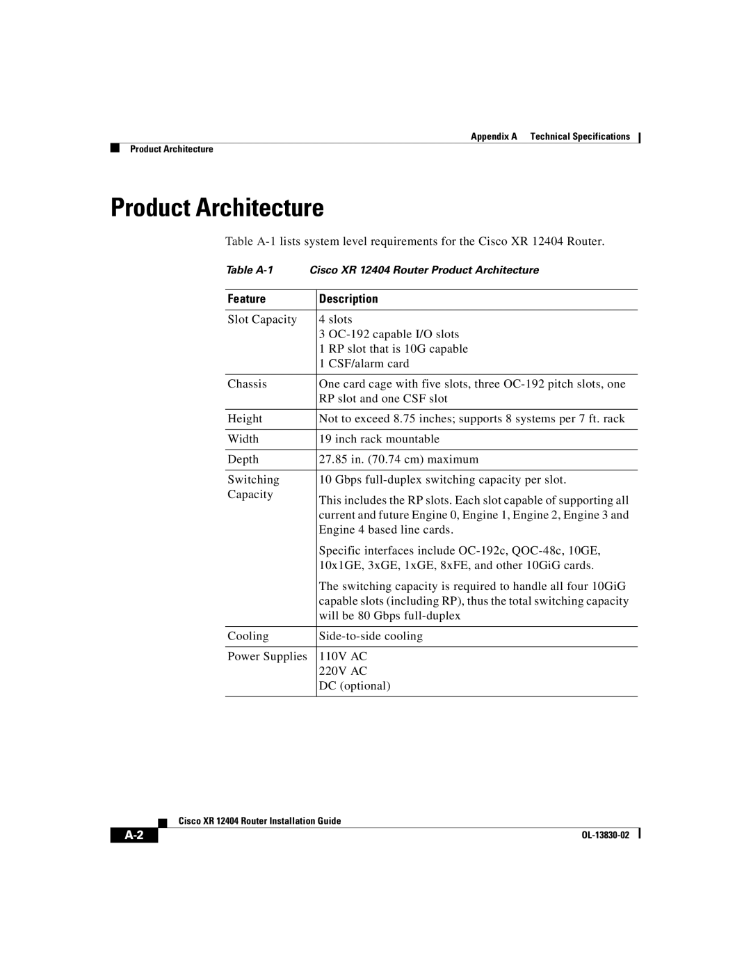
Product Architecture
Table
Table
Feature | Description |
|
|
Slot Capacity | 4 slots |
| 3 |
| 1 RP slot that is 10G capable |
| 1 CSF/alarm card |
|
|
Chassis | One card cage with five slots, three |
| RP slot and one CSF slot |
|
|
Height | Not to exceed 8.75 inches; supports 8 systems per 7 ft. rack |
|
|
Width | 19 inch rack mountable |
|
|
Depth | 27.85 in. (70.74 cm) maximum |
|
|
Switching | 10 Gbps |
Capacity | This includes the RP slots. Each slot capable of supporting all |
| |
| current and future Engine 0, Engine 1, Engine 2, Engine 3 and |
| Engine 4 based line cards. |
| Specific interfaces include |
| 10x1GE, 3xGE, 1xGE, 8xFE, and other 10GiG cards. |
| The switching capacity is required to handle all four 10GiG |
| capable slots (including RP), thus the total switching capacity |
| will be 80 Gbps |
|
|
Cooling | |
|
|
Power Supplies | 110V AC |
| 220V AC |
| DC (optional) |
|
|
| Cisco XR 12404 Router Installation Guide |
|
