CY7C67200
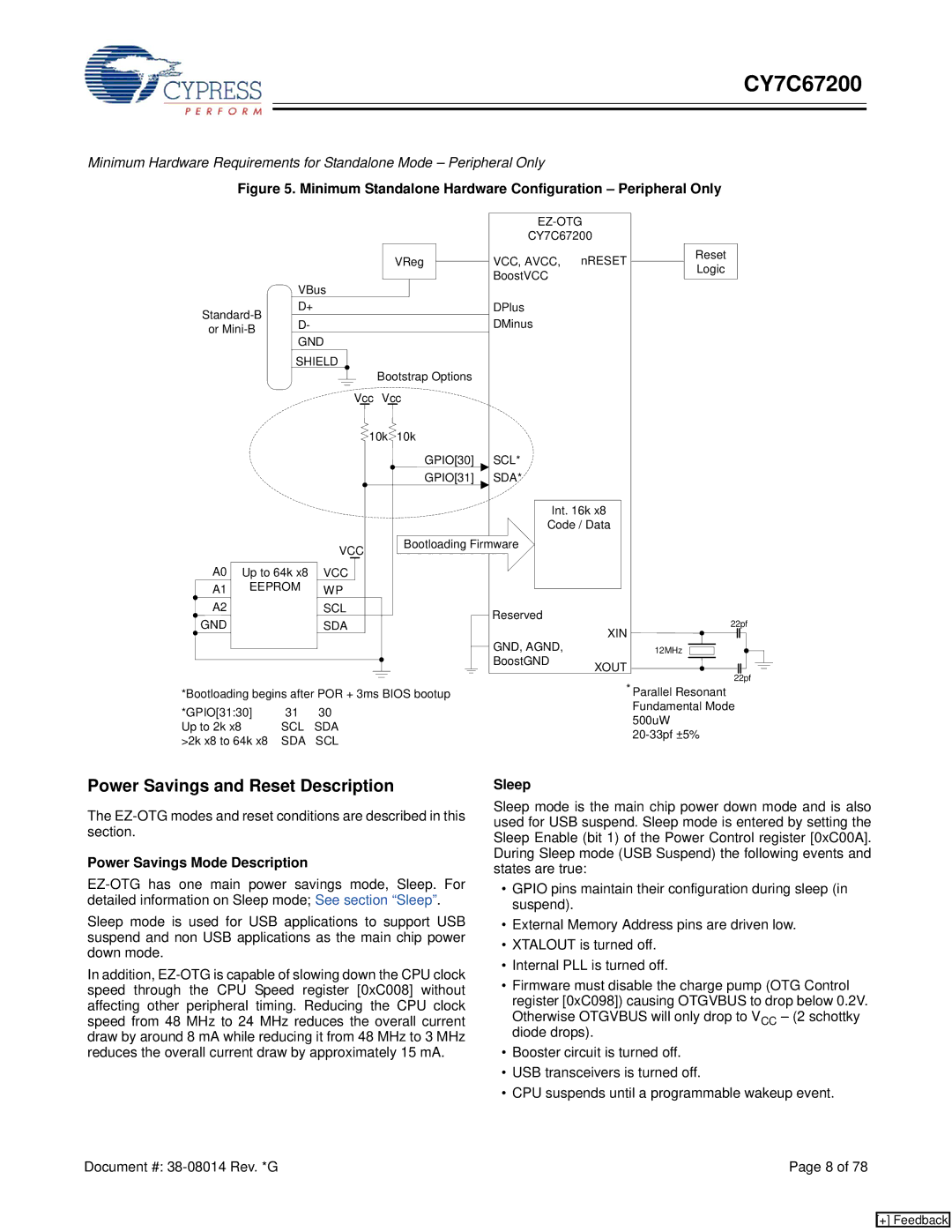
Minimum Hardware Requirements for Standalone Mode – Peripheral Only
Figure 5. Minimum Standalone Hardware Configuration – Peripheral Only
|
|
|
|
|
| ||
|
|
|
|
| CY7C67200 |
| |
|
|
|
| VReg | VCC, AVCC, | nRESET | Reset |
|
|
|
| Logic | |||
|
|
|
|
| BoostVCC |
| |
|
| VBus |
|
|
| ||
|
|
|
|
|
| ||
D+ |
|
| DPlus |
|
| ||
D- |
|
| DMinus |
|
| ||
or |
|
|
|
| |||
GND |
|
|
|
| |||
|
|
|
|
|
| ||
|
| SHIELD |
|
|
|
| |
|
|
| Bootstrap Options |
|
|
| |
|
|
| Vcc Vcc |
|
|
| |
|
|
| 10k | 10k |
|
|
|
|
|
|
| GPIO[30] | SCL* |
|
|
|
|
|
| GPIO[31] | SDA* |
|
|
|
|
|
|
| Int. 16k x8 |
| |
|
|
|
|
| Code / Data |
| |
|
|
| VCC | Bootloading Firmware |
|
| |
|
|
|
|
|
|
| |
A0 Up to 64k x8 | VCC |
|
|
|
| ||
A1 | EEPROM | WP |
|
|
|
| |
A2 |
|
| SCL |
| Reserved |
|
|
GND |
|
| SDA |
|
| 22pf | |
|
|
|
| XIN | |||
|
|
|
|
| GND, AGND, |
| |
|
|
|
|
|
| 12MHz | |
|
|
|
|
| BoostGND | XOUT |
|
|
|
|
|
|
| 22pf | |
|
|
|
|
|
|
| |
*Bootloading begins after POR + 3ms BIOS bootup |
| * Parallel Resonant | |||||
*GPIO[31:30] | 31 | 30 |
|
|
| Fundamental Mode | |
|
|
| 500uW | ||||
Up to 2k x8 |
| SCL | SDA |
|
|
| |
|
|
|
| ||||
>2k x8 to 64k x8 | SDA | SCL |
|
|
| ||
|
|
|
| ||||
Power Savings and Reset Description
The
Power Savings Mode Description
Sleep mode is used for USB applications to support USB suspend and non USB applications as the main chip power down mode.
In addition,
Sleep
Sleep mode is the main chip power down mode and is also used for USB suspend. Sleep mode is entered by setting the Sleep Enable (bit 1) of the Power Control register [0xC00A]. During Sleep mode (USB Suspend) the following events and states are true:
•GPIO pins maintain their configuration during sleep (in suspend).
•External Memory Address pins are driven low.
•XTALOUT is turned off.
•Internal PLL is turned off.
•Firmware must disable the charge pump (OTG Control register [0xC098]) causing OTGVBUS to drop below 0.2V. Otherwise OTGVBUS will only drop to VCC – (2 schottky diode drops).
•Booster circuit is turned off.
•USB transceivers is turned off.
•CPU suspends until a programmable wakeup event.
Document #: | Page 8 of 78 |
[+] Feedback