CY7C67200
HSS Control Register [0xC070] [R/W]
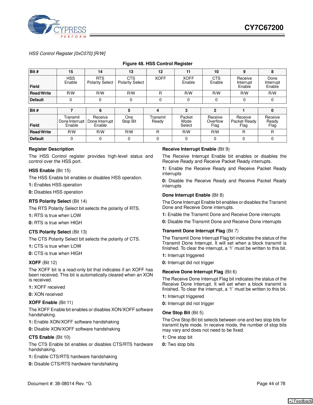
Figure 48. HSS Control Register
Bit # | 15 | 14 | 13 | 12 | 11 | 10 | 9 | 8 |
| HSS | RTS | CTS | XOFF | XOFF | CTS | Receive | Done |
Field | Enable | Polarity Select | Polarity Select |
| Enable | Enable | Interrupt | Interrupt |
|
|
|
|
|
| Enable | Enable | |
Read/Write | R/W | R/W | R/W | R | R/W | R/W | R/W | R/W |
Default | 0 | 0 | 0 | 0 | 0 | 0 | 0 | 0 |
|
|
|
|
|
|
|
|
|
Bit # | 7 | 6 | 5 | 4 | 3 | 2 | 1 | 0 |
| Transmit | Receive | One | Transmit | Packet | Receive | Receive | Receive |
Field | Done Interrupt | Done Interrupt | Stop Bit | Ready | Mode | Overflow | Packet Ready | Ready |
Enable | Enable |
|
| Select | Flag | Flag | Flag | |
Read/Write | R/W | R/W | R/W | R | R/W | R/W | R | R |
Default | 0 | 0 | 0 | 0 | 0 | 0 | 0 | 0 |
|
|
|
|
|
|
|
|
|
Register Description
The HSS Control register provides
HSS Enable (Bit 15)
The HSS Enable bit enables or disables HSS operation.
1:Enables HSS operation
0:Disables HSS operation
RTS Polarity Select (Bit 14)
The RTS Polarity Select bit selects the polarity of RTS.
1:RTS is true when LOW
0:RTS is true when HIGH
CTS Polarity Select (Bit 13)
The CTS Polarity Select bit selects the polarity of CTS.
1:CTS is true when LOW
0:CTS is true when HIGH
XOFF (Bit 12)
The XOFF bit is a
1:XOFF received
0:XON received
XOFF Enable (Bit 11)
The XOFF Enable bit enables or disables XON/XOFF software handshaking.
1:Enable XON/XOFF software handshaking
0:Disable XON/XOFF software handshaking
CTS Enable (Bit 10)
The CTS Enable bit enables or disables CTS/RTS hardware handshaking.
1:Enable CTS/RTS hardware handshaking
0:Disable CTS/RTS hardware handshaking
Receive Interrupt Enable (Bit 9)
The Receive Interrupt Enable bit enables or disables the Receive Ready and Receive Packet Ready interrupts.
1:Enable the Receive Ready and Receive Packet Ready interrupts
0:Disable the Receive Ready and Receive Packet Ready interrupts
Done Interrupt Enable (Bit 8)
The Done Interrupt Enable bit enables or disables the Transmit Done and Receive Done interrupts.
1:Enable the Transmit Done and Receive Done interrupts
0:Disable the Transmit Done and Receive Done interrupts
Transmit Done Interrupt Flag (Bit 7)
The Transmit Done Interrupt Flag bit indicates the status of the Transmit Done Interrupt. It will set when a block transmit is finished. To clear the interrupt, a ‘1’ must be written to this bit.
1:Interrupt triggered
0:Interrupt did not trigger
Receive Done Interrupt Flag (Bit 6)
The Receive Done Interrupt Flag bit indicates the status of the Receive Done Interrupt. It will set when a block transmit is finished. To clear the interrupt, a ‘1’ must be written to this bit.
1:Interrupt triggered
0:Interrupt did not trigger
One Stop Bit (Bit 5)
The One Stop Bit bit selects between one and two stop bits for transmit byte mode. In receive mode, the number of stop bits may vary and does not need to be fixed.
1:One stop bit
0:Two stop bits
Document #: | Page 44 of 78 |
[+] Feedback