u
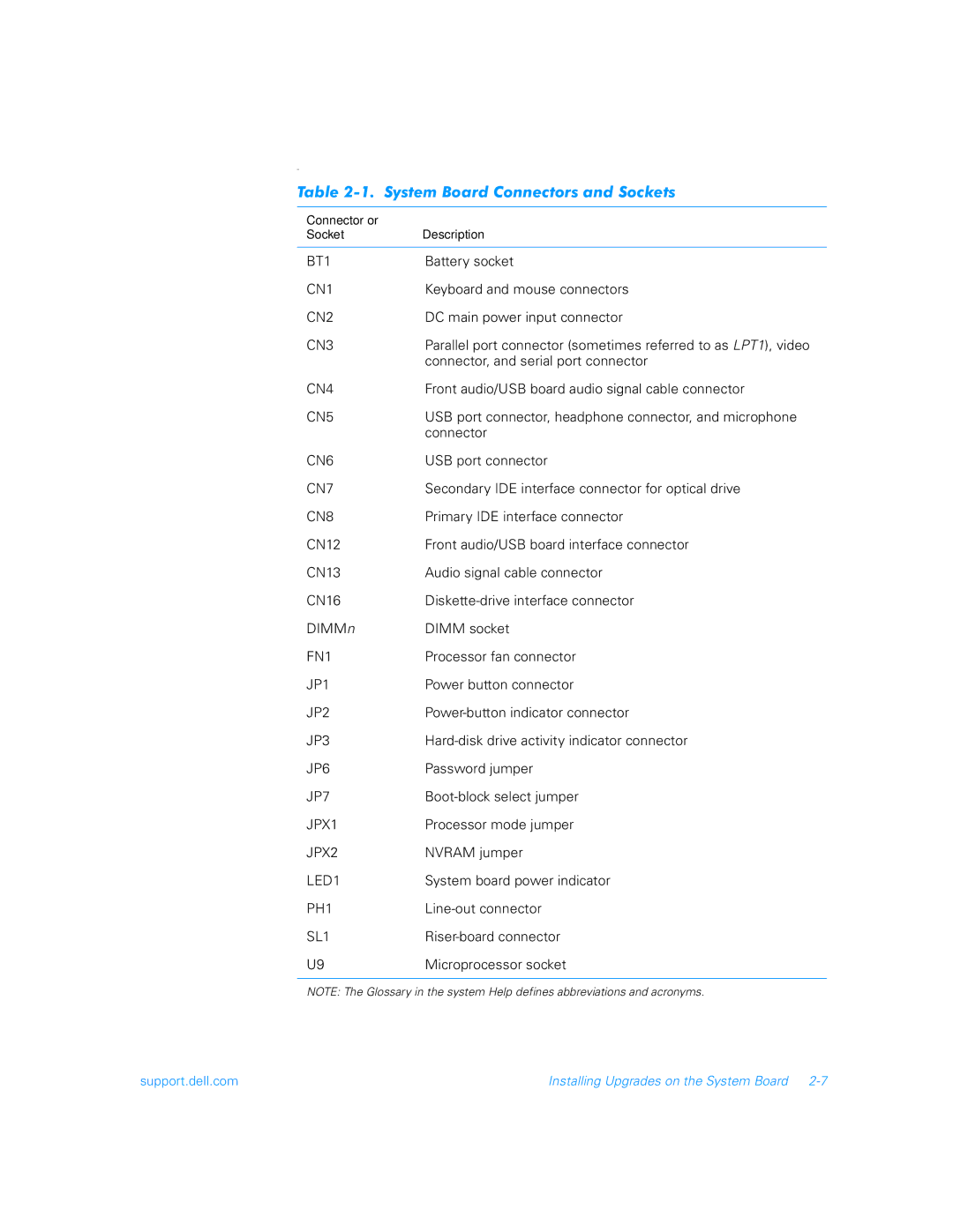
Table 2-1. System Board Connectors and Sockets
Connector or |
|
Socket | Description |
|
|
BT1 | Battery socket |
CN1 | Keyboard and mouse connectors |
CN2 | DC main power input connector |
CN3 | Parallel port connector (sometimes referred to as LPT1), video |
| connector, and serial port connector |
CN4 | Front audio/USB board audio signal cable connector |
CN5 | USB port connector, headphone connector, and microphone |
| connector |
CN6 | USB port connector |
CN7 | Secondary IDE interface connector for optical drive |
CN8 | Primary IDE interface connector |
CN12 | Front audio/USB board interface connector |
CN13 | Audio signal cable connector |
CN16 | |
DIMMn | DIMM socket |
FN1 | Processor fan connector |
JP1 | Power button connector |
JP2 | |
JP3 | |
JP6 | Password jumper |
JP7 | |
JPX1 | Processor mode jumper |
JPX2 | NVRAM jumper |
LED1 | System board power indicator |
PH1 | |
SL1 | |
U9 | Microprocessor socket |
|
|
NOTE: The Glossary in the system Help defines abbreviations and acronyms.
support.dell.com | Installing Upgrades on the System Board |
