Boot-Block Select Jumper
Figure 2-4 shows the location of the boot-block select jumper (JP7) in your computer. Table 2-5 describes the settings and functions of the boot-block select jumper.
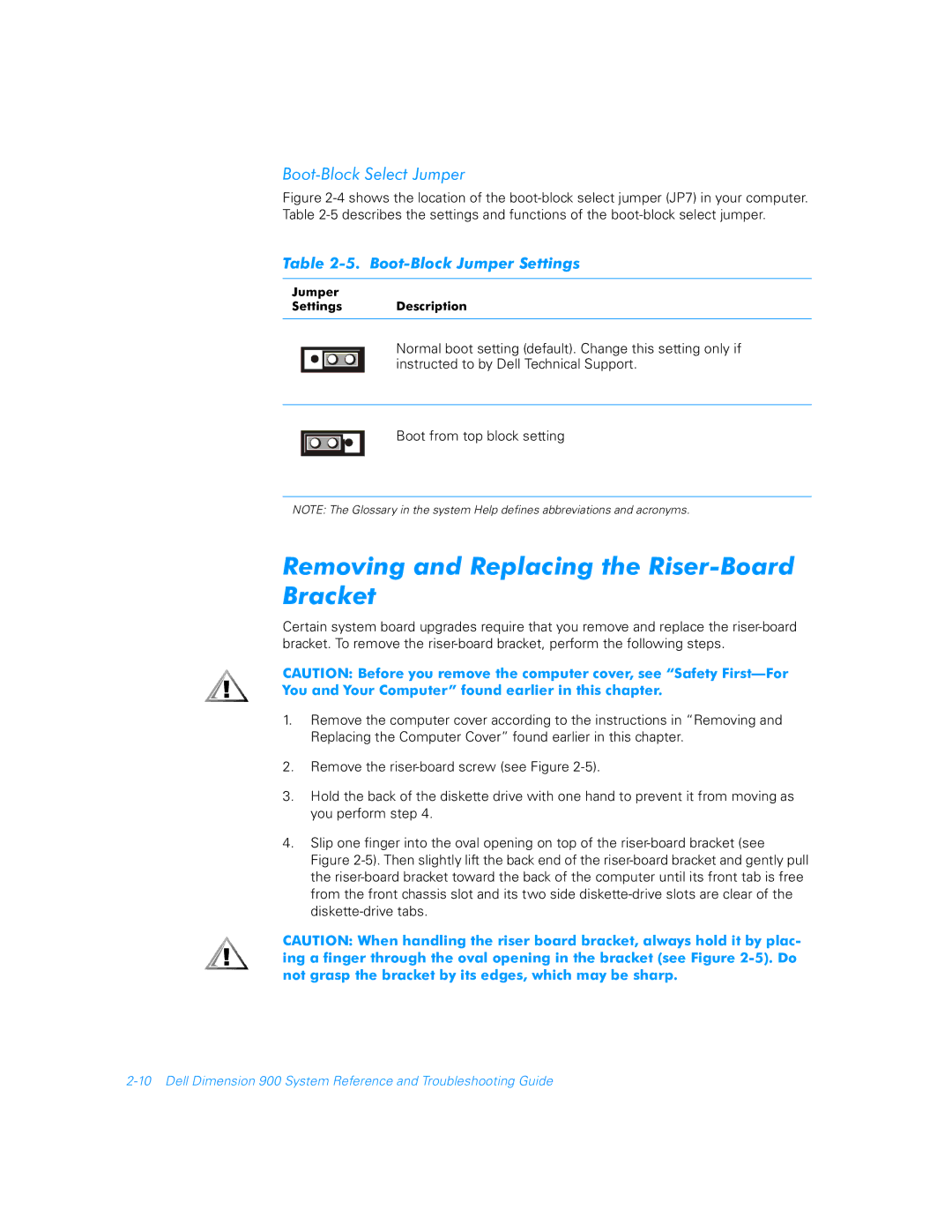
Table 2-5. Boot-Block Jumper Settings
Jumper
Settings Description
Normal boot setting (default). Change this setting only if instructed to by Dell Technical Support.
Boot from top block setting
NOTE: The Glossary in the system Help defines abbreviations and acronyms.
Removing and Replacing the Riser-Board Bracket
Certain system board upgrades require that you remove and replace the
CAUTION: Before you remove the computer cover, see “Safety
1.Remove the computer cover according to the instructions in “Removing and Replacing the Computer Cover” found earlier in this chapter.
2.Remove the
3.Hold the back of the diskette drive with one hand to prevent it from moving as you perform step 4.
4.Slip one finger into the oval opening on top of the
CAUTION: When handling the riser board bracket, always hold it by plac- ing a finger through the oval opening in the bracket (see Figure