Back-Panel Features and Indicators
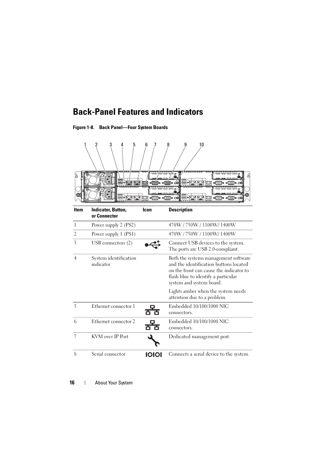
Figure 1-8. Back Panel—Four System Boards
1 | 2 | 3 | 4 | 5 | 6 | 7 | 8 | 9 | 10 |
Item | Indicator, Button, | Icon | Description |
| or Connector |
|
|
1 | Power supply 2 (PS2) |
|
|
|
|
| 470W / 750W / 1100W/ 1400W | ||||||||
|
|
|
|
|
|
|
|
|
|
|
|
|
|
|
|
2 | Power supply 1 (PS1) |
|
|
|
|
| 470W / 750W / 1100W/ 1400W | ||||||||
|
|
|
|
|
|
|
|
|
|
|
|
|
|
|
|
3 | USB connectors (2) |
|
|
|
|
| Connect USB devices to the system. | ||||||||
|
|
|
|
| |||||||||||
|
| ||||||||||||||
|
|
|
|
|
|
|
|
|
|
|
|
|
|
| The ports are USB |
|
|
|
|
|
|
|
|
|
|
|
|
|
|
| |
|
|
|
|
|
|
|
|
|
|
| |||||
|
|
|
|
|
|
|
|
|
|
|
|
|
|
|
|
4 | System identification |
|
|
|
|
| Both the systems management software | ||||||||
| indicator |
|
|
|
|
| and the identification buttons located | ||||||||
|
|
|
|
|
|
|
|
|
|
|
|
|
|
| on the front can cause the indicator to |
|
|
|
|
|
|
|
|
|
|
|
|
|
|
| flash blue to identify a particular |
|
|
|
|
|
|
|
|
|
|
|
|
|
|
| system and system board. |
|
|
|
|
|
|
|
|
|
|
|
|
|
|
| Lights amber when the system needs |
|
|
|
|
|
|
|
|
|
|
|
|
|
|
| attention due to a problem. |
|
|
|
|
|
|
|
|
|
|
|
|
|
|
|
|
5 | Ethernet connector 1 |
|
|
|
|
|
|
|
|
| Embedded 10/100/1000 NIC | ||||
|
|
|
|
|
|
|
|
|
|
|
|
|
|
| connectors. |
|
|
|
|
|
|
|
|
|
|
|
|
|
|
|
|
6 | Ethernet connector 2 |
|
|
|
|
|
|
|
|
| Embedded 10/100/1000 NIC | ||||
|
|
|
|
|
|
|
|
|
|
|
|
|
|
| connectors. |
|
|
|
|
|
|
|
|
|
|
|
|
|
|
|
|
7 | KVM over IP Port |
|
|
|
|
| Dedicated management port. | ||||||||
|
|
|
|
|
|
|
|
|
|
|
|
|
|
|
|
8 | Serial connector |
|
|
|
|
|
|
|
|
| Connects a serial device to the system. | ||||
|
|
|
|
|
| ||||||||||
16
About Your System
