Fluke 8842a instruction manual TRACK/HOLD Circuit, Track/Hold Amplifier

Models: 8842a

1 269
Download 269 pages 45.95 Kb
Page 115
Image 115

8842A

Instruction Manual

5-9. TRACK/HOLD CIRCUIT

The Track/Hold (T/H) circuit presents a stable voltage to the A/D Converter during the input period of the A/D conversion cycle. The circuit also provides a gain of 100 in the

20 mV, 20Ω and 200 mA ranges, and a gain of 10 in the 200 mV dc, 200Ω, and 2000 mA dc ranges.

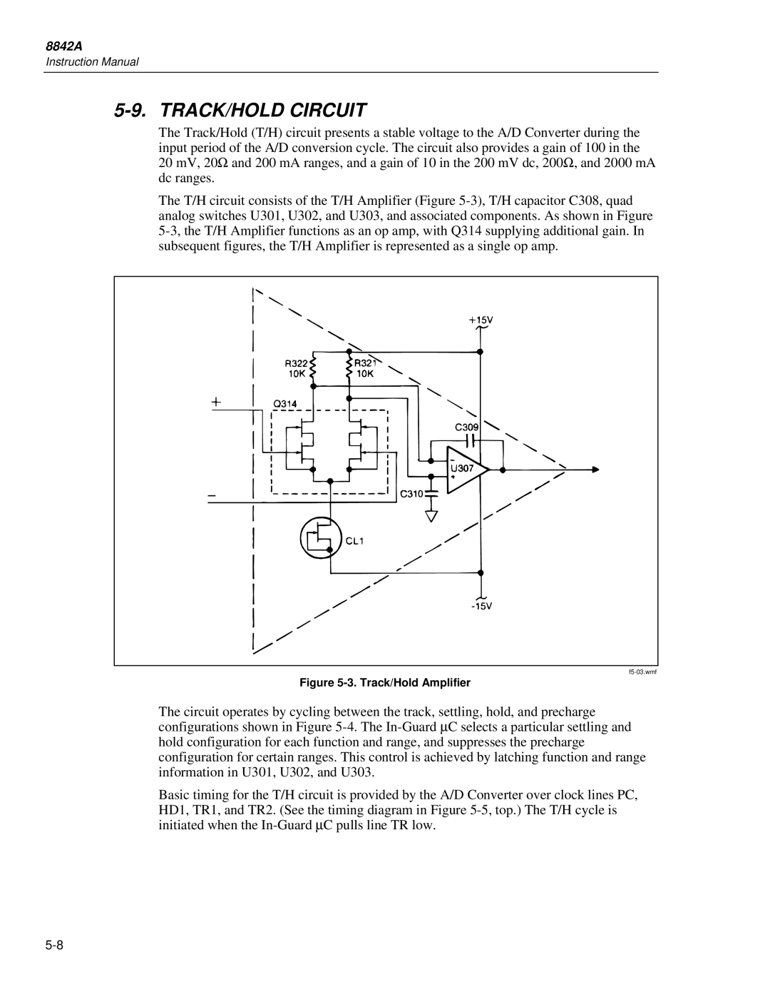
The T/H circuit consists of the T/H Amplifier (Figure 5-3), T/H capacitor C308, quad analog switches U301, U302, and U303, and associated components. As shown in Figure 5-3, the T/H Amplifier functions as an op amp, with Q314 supplying additional gain. In subsequent figures, the T/H Amplifier is represented as a single op amp.

f5-03.wmf

Figure 5-3. Track/Hold Amplifier

The circuit operates by cycling between the track, settling, hold, and precharge configurations shown in Figure 5-4. The In-Guard μC selects a particular settling and hold configuration for each function and range, and suppresses the precharge configuration for certain ranges. This control is achieved by latching function and range information in U301, U302, and U303.

Basic timing for the T/H circuit is provided by the A/D Converter over clock lines PC, HD1, TR1, and TR2. (See the timing diagram in Figure 5-5, top.) The T/H cycle is initiated when the In-Guard μC pulls line TR low.

5-8

Page 115
Image 115
Fluke 8842a instruction manual TRACK/HOLD Circuit, Track/Hold Amplifier