Maintenance 6
CALIBRATION
If ERROR 41 occurs, the most likely cause is that the reference input is incorrect (e.g., has the wrong polarity). If the input is in fact correct, refer to the Troubleshooting heading in this section.
1.
2.
3.
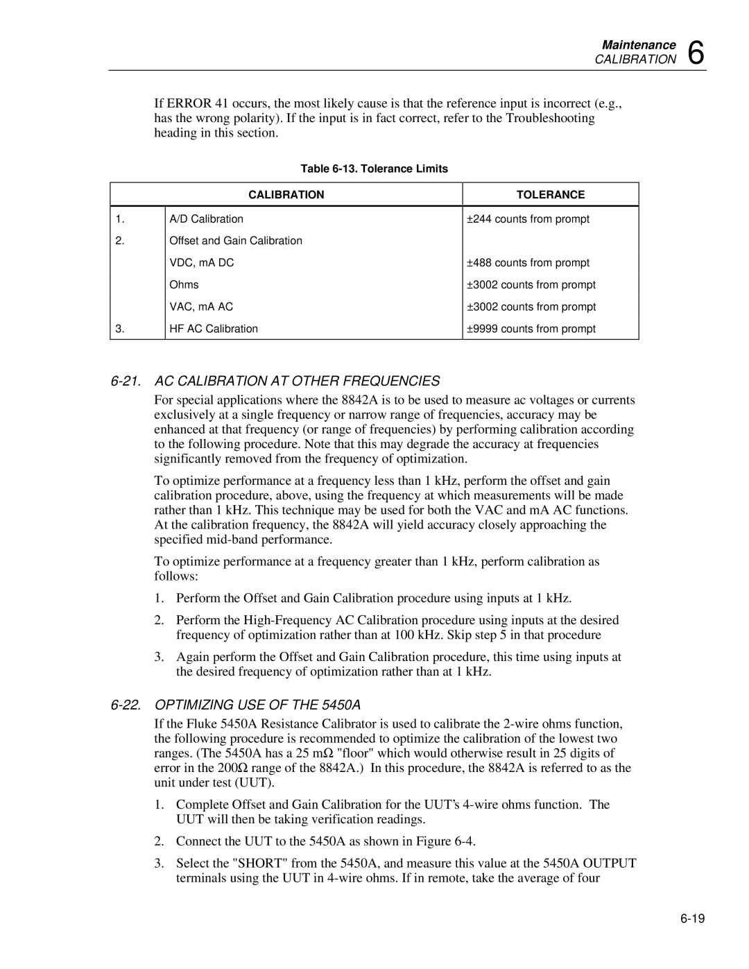
Table
CALIBRATION
A/D Calibration
Offset and Gain Calibration
VDC, mA DC
Ohms
VAC, mA AC
HF AC Calibration
TOLERANCE
±244 counts from prompt
±488 counts from prompt ±3002 counts from prompt ±3002 counts from prompt ±9999 counts from prompt
6-21. AC CALIBRATION AT OTHER FREQUENCIES
For special applications where the 8842A is to be used to measure ac voltages or currents exclusively at a single frequency or narrow range of frequencies, accuracy may be enhanced at that frequency (or range of frequencies) by performing calibration according to the following procedure. Note that this may degrade the accuracy at frequencies significantly removed from the frequency of optimization.
To optimize performance at a frequency less than 1 kHz, perform the offset and gain calibration procedure, above, using the frequency at which measurements will be made rather than 1 kHz. This technique may be used for both the VAC and mA AC functions. At the calibration frequency, the 8842A will yield accuracy closely approaching the specified
To optimize performance at a frequency greater than 1 kHz, perform calibration as follows:
1.Perform the Offset and Gain Calibration procedure using inputs at 1 kHz.
2.Perform the
3.Again perform the Offset and Gain Calibration procedure, this time using inputs at the desired frequency of optimization rather than at 1 kHz.
6-22. OPTIMIZING USE OF THE 5450A
If the Fluke 5450A Resistance Calibrator is used to calibrate the
1.Complete Offset and Gain Calibration for the UUT’s
2.Connect the UUT to the 5450A as shown in Figure
3.Select the "SHORT" from the 5450A, and measure this value at the 5450A OUTPUT terminals using the UUT in