Fluke 8842a instruction manual Evaluating Dynamic Signals, DC Scaling Troubleshooting

Models: 8842a

1 269
Download 269 pages 45.95 Kb
Page 191
Image 191

8842A

Instruction Manual

If the instrument is not in the slow reading rate, it gives the following pattern at U305-5:

000000 00000 000000 0000000 000

Next move to U305-7 and repeat. The pattern at U305-7 will be:

000000 00000 000000 1111111 000

6-61. Evaluating Dynamic Signals

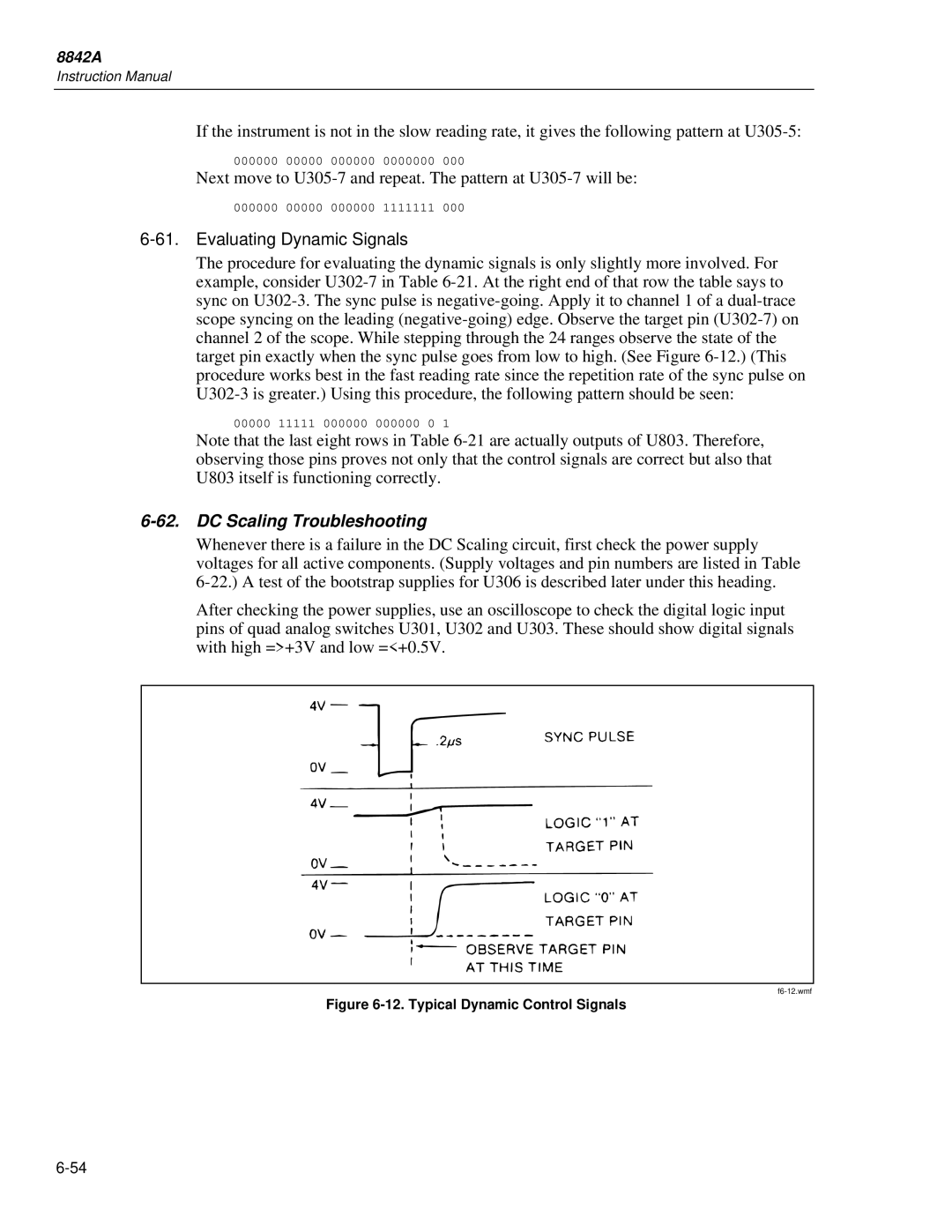
The procedure for evaluating the dynamic signals is only slightly more involved. For example, consider U302-7 in Table 6-21. At the right end of that row the table says to sync on U302-3. The sync pulse is negative-going. Apply it to channel 1 of a dual-trace scope syncing on the leading (negative-going) edge. Observe the target pin (U302-7) on channel 2 of the scope. While stepping through the 24 ranges observe the state of the target pin exactly when the sync pulse goes from low to high. (See Figure 6-12.) (This procedure works best in the fast reading rate since the repetition rate of the sync pulse on

U302-3 is greater.) Using this procedure, the following pattern should be seen:

00000 11111 000000 000000 0 1

Note that the last eight rows in Table 6-21 are actually outputs of U803. Therefore, observing those pins proves not only that the control signals are correct but also that U803 itself is functioning correctly.

6-62. DC Scaling Troubleshooting

Whenever there is a failure in the DC Scaling circuit, first check the power supply voltages for all active components. (Supply voltages and pin numbers are listed in Table 6-22.) A test of the bootstrap supplies for U306 is described later under this heading.

After checking the power supplies, use an oscilloscope to check the digital logic input pins of quad analog switches U301, U302 and U303. These should show digital signals with high =>+3V and low =<+0.5V.

f6-12.wmf

Figure 6-12. Typical Dynamic Control Signals

6-54

Page 191
Image 191
Fluke 8842a instruction manual Evaluating Dynamic Signals, DC Scaling Troubleshooting