Maintenance 6
TROUBLESHOOTING
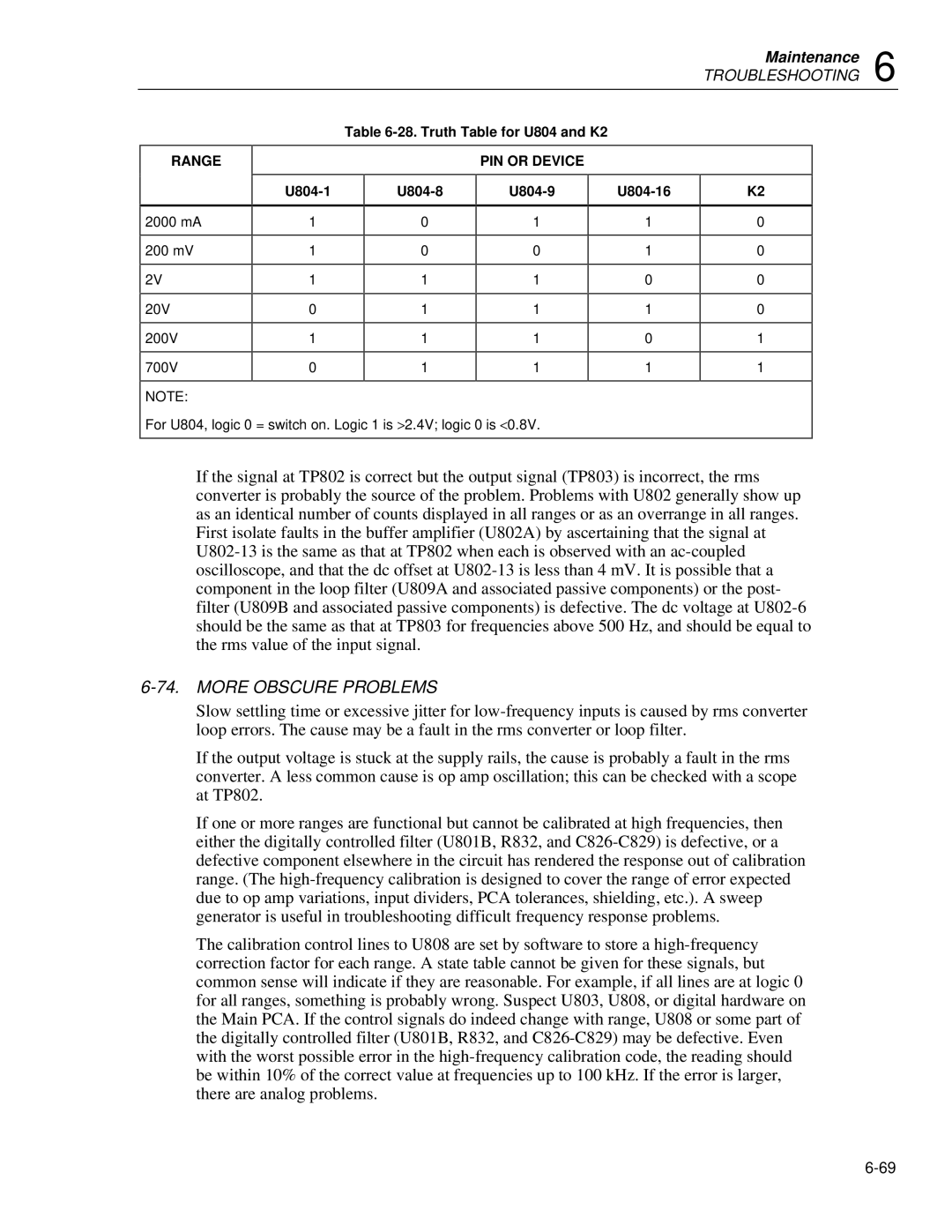
Table 6-28. Truth Table for U804 and K2
PIN OR DEVICE
| U804-1 | | U804-8 | | U804-9 | | U804-16 | | K2 | |
| | | | | |
| | | | | | | | | | |
2000 mA | 1 | 0 | 1 |
| | | |
200 mV | 1 | 0 | 0 |
| | | |
2V | 1 | 1 | 1 |
| | | |
20V | 0 | 1 | 1 |
| | | |
200V | 1 | 1 | 1 |
| | | |
700V | 0 | 1 | 1 |
| | | |
NOTE:
For U804, logic 0 = switch on. Logic 1 is >2.4V; logic 0 is <0.8V.
If the signal at TP802 is correct but the output signal (TP803) is incorrect, the rms converter is probably the source of the problem. Problems with U802 generally show up as an identical number of counts displayed in all ranges or as an overrange in all ranges. First isolate faults in the buffer amplifier (U802A) by ascertaining that the signal at U802-13 is the same as that at TP802 when each is observed with an ac-coupled oscilloscope, and that the dc offset at U802-13 is less than 4 mV. It is possible that a component in the loop filter (U809A and associated passive components) or the post- filter (U809B and associated passive components) is defective. The dc voltage at U802-6 should be the same as that at TP803 for frequencies above 500 Hz, and should be equal to the rms value of the input signal.
6-74. MORE OBSCURE PROBLEMS
Slow settling time or excessive jitter for low-frequency inputs is caused by rms converter loop errors. The cause may be a fault in the rms converter or loop filter.
If the output voltage is stuck at the supply rails, the cause is probably a fault in the rms converter. A less common cause is op amp oscillation; this can be checked with a scope at TP802.
If one or more ranges are functional but cannot be calibrated at high frequencies, then either the digitally controlled filter (U801B, R832, and C826-C829) is defective, or a defective component elsewhere in the circuit has rendered the response out of calibration range. (The high-frequency calibration is designed to cover the range of error expected due to op amp variations, input dividers, PCA tolerances, shielding, etc.). A sweep generator is useful in troubleshooting difficult frequency response problems.
The calibration control lines to U808 are set by software to store a high-frequency correction factor for each range. A state table cannot be given for these signals, but common sense will indicate if they are reasonable. For example, if all lines are at logic 0 for all ranges, something is probably wrong. Suspect U803, U808, or digital hardware on the Main PCA. If the control signals do indeed change with range, U808 or some part of the digitally controlled filter (U801B, R832, and C826-C829) may be defective. Even with the worst possible error in the high-frequency calibration code, the reading should be within 10% of the correct value at frequencies up to 100 kHz. If the error is larger, there are analog problems.