Remote Programming 3
OUTPUT DATA
Because the 8842A gives priority to input processing, it completely processes all characters in the input buffer before it loads the output buffer. When the output buffer is loaded, the Data Available bit in the serial poll register is set true.
Data from the output buffer is not actually loaded onto the
3-42. Types of Output Data
The types of data that can be loaded into the output buffer are shown in Figure
3-43. Numeric Data and Error Messages
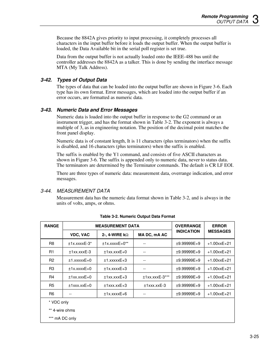
Numeric data is loaded into the output buffer in response to the G2 command or an instrument trigger, and has the format shown in Table
Numeric data is of constant length, It is 11 characters (plus terminators) when the suffix is disabled, and 16 characters (plus terminators) when the suffix is enabled.
The suffix is enabled by the Y1 command, and consists of five ASCII characters as shown in Figure
There are three types of numeric data: measurement data, overrange indication, and error messages.
3-44. MEASUREMENT DATA
Measurement data has the numeric data format shown in Table
Table
RANGE |
| MEASUREMENT DATA | ||
|
|
|
|
|
| VDC, VAC |
| MA DC, mA AC | |
|
|
|
|
|
OVERRANGE INDICATION
ERROR
MESSAGES
R8 | |
|
|
R1 | |
|
|
R2 | ±1.xxxxxE+0 |
|
|
R3 | ±1x.xxxxE+0 |
|
|
R4 | ±1xx.xxxE+0 |
|
|
R5 | ±1xxx.xxE+0 |
|
|
R6 | |
|
|
*VDC only
**
***mA DC only
±1x.xxxxE+0**
±1xx.xxxE+0
±1.xxxxxE+3
±1x.xxxxE+3
±1xx.xxxE+3
±1xxx.xxE+3
±1x.xxxxE+6
±9.99999E+9
±9.99999E+9
±9.99999E+9
±9.99999E+9
±9.99999E+9
±9.99999E+9
±9.99999E+9
+1.00xxE+21
+1.00xxE+21
+1.00xxE+21
+1.00xxE+21
+1.00xxE+21
+1.00xxE+21
+1.00xxE+21
