8842A
Instruction Manual
5-32. Keyboard/Display Control
Keyboard/Display Controller U212 communicates with the In-Guard μC over the internal bus. During a μC write cycle, address line A0 tells U212 whether to consider data being sent by the μC as configuration commands or as display data. Display data is stored in the Keyboard/Display Controller, which automatically scans the display. The Keyboard/Display Controller selects one of eight grids using decoder U213 and buffer U215. The numeric display data is decoded from BCD to 7-segment by decoder U216 and buffered by U217. Additional annunciator data is buffered by U218.
The Keyboard/Display Controller is reset by the μC whenever the μC is reset. It receives a 1-MHz clock signal from the custom A/D IC (U101), which uses the μC 8-MHz crystal for its clock input.
The Keyboard/Display Controller scans the keyboard, sensing pressed buttons on lines RL0-RL7. It sends an interrupt to the μC via line KEYINT whenever a front panel button is pressed. The μC then reads the keycode from the Keyboard/Display Controller. (The status of the FRONT/REAR switch is sensed separately by line F/R SENSE.)
5-33. Troubleshooting Modes
In addition to running the diagnostic self-tests, the In-Guard μC has a troubleshooting mode which aids in finding digital hardware problems. After the uC is reset, it senses the relay control lines (U202-35 through U202-38) as inputs. If line U202-38 (TP205) is shorted to ground, the μC goes into the troubleshooting mode. (U201 provides internal pull-up.) The troubleshooting mode is described in detail in the Maintenance section.
5-34. Guard-Crossing Communication
The In-Guard μC contains a UART (universal asynchronous receiver transmitter) which it uses to communicate across the guard to the IEEE-488 Interface. The transmission speed is 62,500 bits per second.
5-35. GUARD CROSSING
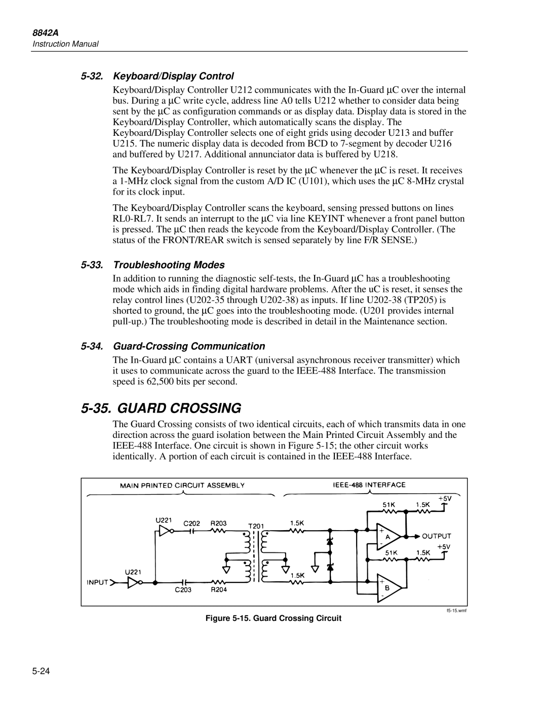
The Guard Crossing consists of two identical circuits, each of which transmits data in one direction across the guard isolation between the Main Printed Circuit Assembly and the IEEE-488 Interface. One circuit is shown in Figure 5-15; the other circuit works identically. A portion of each circuit is contained in the IEEE-488 Interface.
Figure 5-15. Guard Crossing Circuit