8842A
Instruction Manual
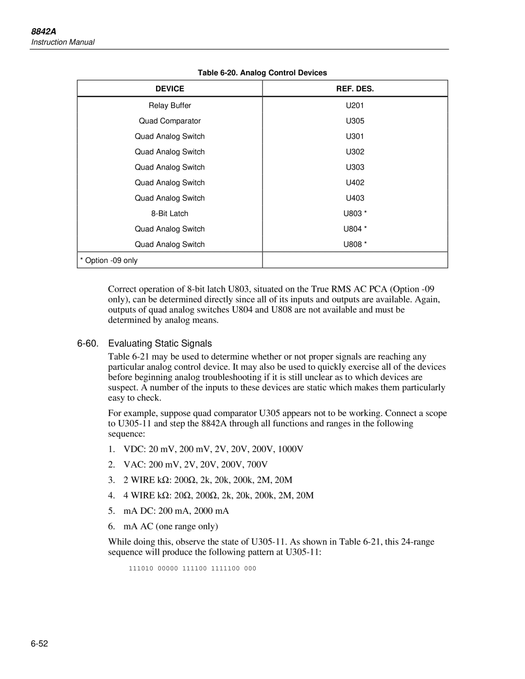
Table
DEVICE
REF. DES.
Relay Buffer
Quad Comparator
Quad Analog Switch
Quad Analog Switch
Quad Analog Switch
Quad Analog Switch
Quad Analog Switch
Quad Analog Switch
Quad Analog Switch
* Option
U201
U305
U301
U302
U303
U402
U403
U803 *
U804 *
U808 *
Correct operation of
6-60. Evaluating Static Signals
Table
For example, suppose quad comparator U305 appears not to be working. Connect a scope to
1.VDC: 20 mV, 200 mV, 2V, 20V, 200V, 1000V
2.VAC: 200 mV, 2V, 20V, 200V, 700V
3.2 WIRE kΩ: 200Ω, 2k, 20k, 200k, 2M, 20M
4.4 WIRE kΩ: 20Ω, 200Ω, 2k, 20k, 200k, 2M, 20M
5.mA DC: 200 mA, 2000 mA
6.mA AC (one range only)
While doing this, observe the state of
111010 00000 111100 1111100 000