Fluke 8842a Installation, Installing the Power-Line Fuse, Connecting to Line Power

Models: 8842a

1 269
Download 269 pages 45.95 Kb
Page 27
Image 27

8842A

Instruction Manual

2-1. INTRODUCTION

This section provides instructions for installing and operating the 8842A. Refer to

Section 4 for measurement considerations.

2-2. INSTALLATION

2-3. Installing the Power-Line Fuse

WARNING

FOR POWER-LINE VOLTAGES OF 198V TO 250V, THE POWER-

LINE FUSE MUST BE REPLACED WITH A 1/8A, 250V SLO-BLO

FUSE FOR FIRE PROTECTION. TO AVOID ELECTRIC SHOCK,

REMOVE THE POWER CORD BEFORE REPLACING THE

EXTERNAL LINE FUSE.

The 8842A has a rear-panel power-line fuse in series with the power supply. A 1/4A, 250V slow-blow fuse is installed in the factory for operation from 90V to 132V. For operation with power-line voltages of 198V to 250V, the fuse must be replaced with a 1/8A, 250V slo-blow fuse.

To replace the power-line fuse, first remove the power cord. Then turn the rear-panel fuse cover 1/4-turn counterclockwise with a screwdriver.

For power-line voltages of 198V to 250V, use only a 1/4 x 1 1/4 (6.3mm x 32mm) fuse with at least a 100A breaking capacity.

2-4. Connecting to Line Power

WARNING

TO AVOID SHOCK HAZARD, CONNECT THE INSTRUMENT

POWER CORD TO A POWER RECEPTACLE WITH EARTH

GROUND. TO AVOID INSTRUMENT DAMAGE, CHECK THAT

THE REAR PANEL LINE VOLTAGE SELECTION SWITCHES ARE

SET TO THE POWER-LINE VOLTAGE IN OUR AREA.

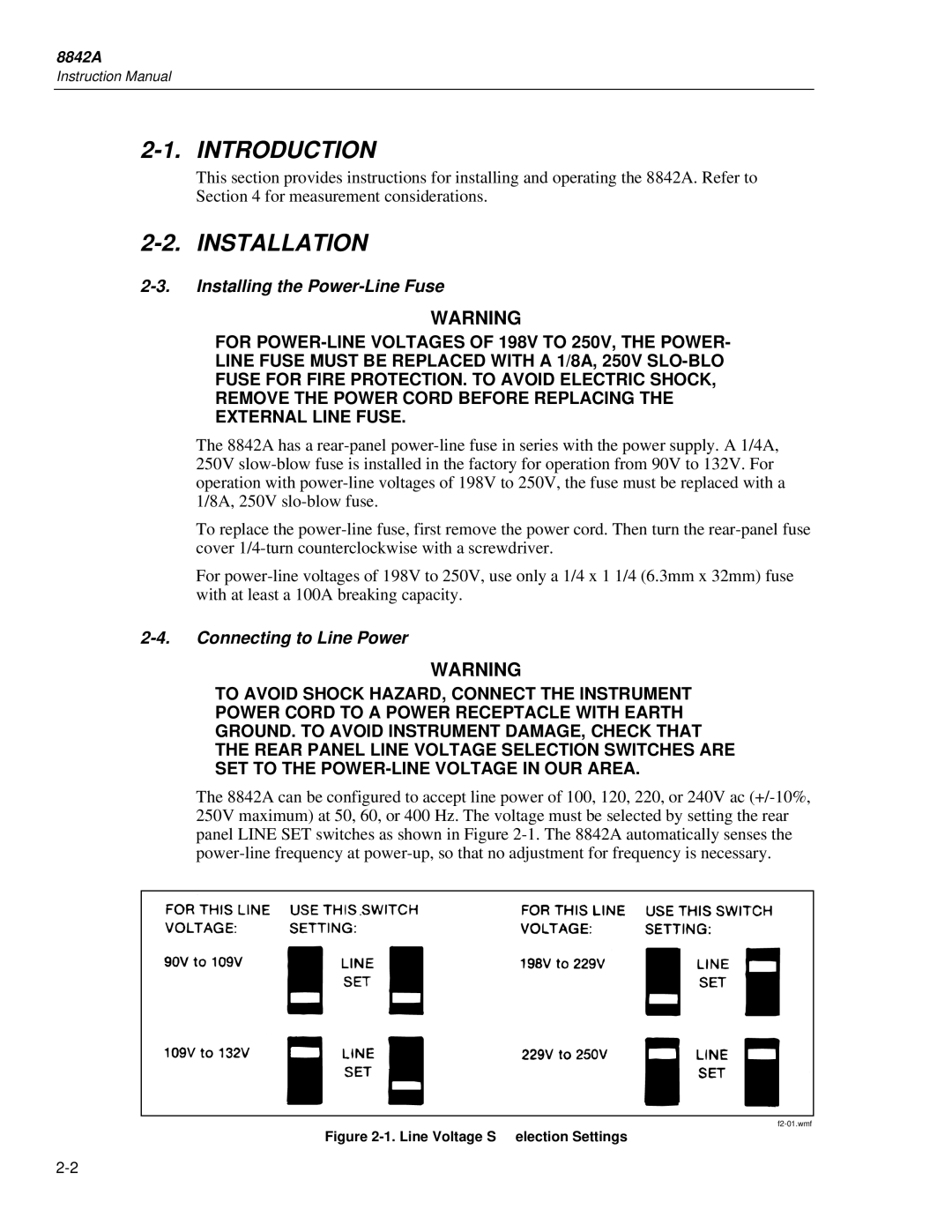
The 8842A can be configured to accept line power of 100, 120, 220, or 240V ac (+/-10%, 250V maximum) at 50, 60, or 400 Hz. The voltage must be selected by setting the rear panel LINE SET switches as shown in Figure 2-1. The 8842A automatically senses the power-line frequency at power-up, so that no adjustment for frequency is necessary.

f2-01.wmf

Figure 2-1. Line Voltage S election Settings

2-2

Page 27
Image 27
Fluke 8842a instruction manual Installation, Installing the Power-Line Fuse, Connecting to Line Power