Manuals
/
Fujitsu
/
Computer Equipment
/
Server
Fujitsu
RX600 S5
manual
Carefully fold up and latch the locking bail
Models:
RX600 S5
1
131
148
148
Download
148 pages
12.99 Kb
128
129
130
131
132
133
134
135
Troubleshooting
Install
Error codes
Timer-controlled switch-on/off
ID indicator and button
Connecting the monitor
Dimension
Configuring the server
Accessible drives/components
Bios Setup security functions
Page 131
Image 131
CSS components
Non-hot-plug
components
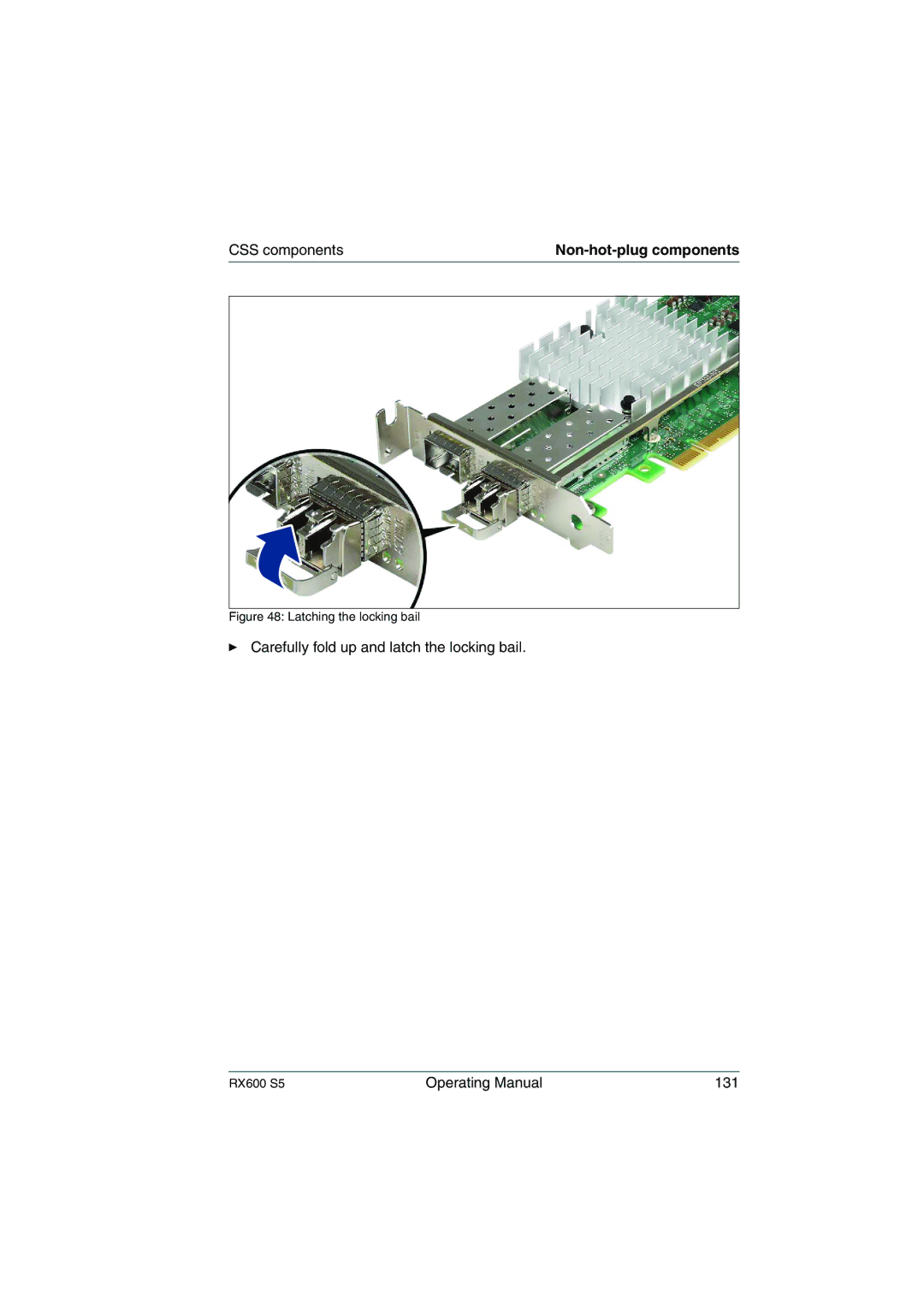
Figure 48: Latching the locking bail
Ê
Carefully fold up and latch the locking bail.
RX600 S5
Operating Manual
131
Page 130
Page 132
Page 131
Image 131
Page 130
Page 132
Contents
Primergy RX600 S5 Server
Certified documentation according to DIN EN ISO
Comments… Suggestions… Corrections…
Copyright and Trademarks
Aluminum electrolytic capacitors
For your safety
High safety use
Radio interference
Only for the Japanese market About Sata hard disk drives
Measures against momentary voltage drop
Harmonic Current Standards
Only for the Japanese market
Operating Manual
Contents
Control elements and indicators
Contents
Non-hot-plug components
Opening/Closing the server
Concept and target groups for this manual
Preface
Documentation overview Preface
Documentation overview
Further sources of information
Customer Self Service CSS
Features
Features Preface
Hot-plug PCI slots
Battery Backup Units
Accessible drives/components
System board
High level of availability and data security
Power supply
Cooling
Preface
Operating Manual
Server management
Service and support
Features Preface ServerView Installation Manager
ServerView Remote Management
Notational conventions Preface
Technical data
Electrical data hot-plug power supply unit
Notational conventions
Compliance with regulations and standards
Ambient conditions
Technical data
Dimensions / Weight
Ventilation clearance
Overview of the installation steps
Overview of the installation steps
Important information
Safety instructions
Before starting up
Safety instructions
Installation and operation
Important information
Safety instructions
Batteries
Working with CDs/DVDs/BDs and optical drives
Never remove parts of the optical drive casing
Laser information
ESD label
Modules with Electrostatic-Sensitive Devices
Other important information
CE conformity
FCC Class a Compliance Statement
FCC Class a Compliance Statement
Transporting the server
For the Japanese market, please refer to 安全上の注意およびその 他の重要情報
Packaging information
Environmental protection
Environmentally-friendly product design and development
Energy-saving information
Returns, recycling and disposal
Environmental protection
Labels on plastic casing parts
Hours
Minimum acclimatization time
Unpacking the server
Unpacking the server
Fujitsu rack systems
Rack installation/removal of server
Hardware installation
Rack system requirements
3rd party racks
Rack installation/removal of server
Mechanical requirements RX600 S5
Installation in PRIMECENTER/DataCenter rack
Fitting the support bracket
Fitting the support bracket
Installing the support systems
Vcaution
Inserting the server a
Inserting the server
For the Japanese market, please refer to 安全上の注意およびその他の 重要情報
Installation in 3rd party racks
Racks with installation depth smaller/greater than 735 mm
Racks with installation depth of 735 mm
Connectors on the front
Connecting devices to the server
Connecting the monitor
Connecting devices to the server
PSU Configuration Max. DC Loading DC Redundancy
Connecting the server to the mains
Installation requirements
Installation requirements for AC redundant configurations
Connecting the server to the mains
Installation in PRIMECENTER/Datacenter rack
Connecting the server to the mains
Photo shows installation of a protective earth conductor
Cable clamps to secure the power cords
Connecting the power cord
Disconnecting cables
Connecting cables
Operating Manual
Front of server
Control elements and indicators
Front detailed view control panel
ID card
Control elements
Starting up and operation
Indicators on the control panel
Control elements and indicators
ServerView Local Service Display
Indicators on a hot-plug HDD module
Indicators on the hot-plug HDD modules
Rear of server
Global Error indicator and CSS indicator
Control elements and indicators
ID indicator
ID indicator and button
LAN
Indicators on the connector panel LAN indicators
LAN link/transfer management LAN
Indicators on the hot-plug power supply units
Control elements and indicators
Starting up for the first time
Switching the server on and off
Switching the server on
Timer-controlled switch-on/off
Switching the server on and off
System already installed
Switching the server off
IRMC S2
Configuring the server
Configuring the server
Configuring the SAS/SATA RAID controller card
Advantages of the ServerView Installation Manager
Installing the operating system
Cleaning the server
Cleaning the server
Bios Setup security functions
Mechanical access protection
Bios Setup security functions
Power supply overloaded
Power-on indicator remains unlit
Power cable incorrectly connected
Screen remains blank
Server switches itself off
Monitor does not support the set horizontal frequency
Troubleshooting and tips
Flickering stripes on monitor screen
No screen display or display drifts
Incorrect date and time
Drives reported as dead when starting system
RAID controller configuration incorrect
Incorrect date and time
Added drive reported as defective
Error message on screen
RAID controller is not configured for this drive
Error message on screen
CSS components
RX600 S5
CSS components
Hot-plug power supply units
Hot-plug components
Hot-plug components
Replacing a hot-plug power supply unit
Removing a PSU dummy module
Adding a hot-plug power supply unit
Hot-plug components
Identifying the defective CSS component
Hot-plug fans
Unlocking a fan module and removing it
Replacing a defective fan
Adding new fans
Hot-plug HDD modules
Handling drives and HDD/SSD modules
5-inch HDD module and dummy module
3.1 HDD/SSD module and dummy module
Removing/installing the 2.5-inch dummy module
Removing/installing the dummy module
Unlocking the 2.5-inch HDD module
Installing the HDD module
Removing the HDD module
Installing the 2.5-inch HDD module
Hot-plug components
Hot-plug expansion cards
PCI slots with and without hot-plug functionality
Slot # Description
Deactivating, unlocking and removing the board
Removing a hot-plug expansion card
Removing the expansion card from the removal tool
Removing an expansion card from the removal tool
Removing engaging hooks from the removal tool
Removing engaging hooks
Removing the retaining plate from the removal tool
Removing a dummy module
Operating Manual 113
Operating the expansion card
Hot-plug memory boards
Open the server see Opening the server on
Identifying the defective memory
Removing a defective memory module
Removing the memory board in question
Removing a memory module
Reinstalling the memory board in question
Installing a new memory module
Removing the memory air baffle to add a memory board
Adding a memory board
Non-hot-plug components
Removing a non-hot-plug expansion card
Identifying the defective CSS component
Replacing a non-hot-plug expansion card
Non-hot-plug components
Take the expansion card out and put it aside
Removing engaging hooks
Installing a non-hot-plug expansion card
Removing an SFP+ transceiver module
Replacing SFP+ transceiver modules
Operating Manual 127
Removing the SFP+ transceiver
Installing SFP+ transceiver modules
Inserting the SFP+ transreiver
Carefully fold up and latch the locking bail
Attaching the protective optical port plug
Operating Manual 133
Opening/Closing the server
Opening/Closing the server
Opening the server
Operating Manual 135
Closing the server
Placing the housing cover
Processor
Memory Modules Configuration
Slots
Interfaces
Onboard or integrated controllers
Operating Panel
Drive bays
General system information
Environmental
Dimensions Base unit specific
Electrical values
Appendix server specification 142 Operating Manual
Index
Energy Star
Index
Integrated Remote Management
126
Using cable clamps Video connector Voltage Voltage range
148 Operating Manual
Top
Page
Image
Contents