Description | Spare part number | ||
|
|
|
|
G465, | 1.9 | GHz, | |
|
|
|
|
G460, | 1.8 | GHz, | |
|
|
|
|
1.Prepare the computer for disassembly (Preparation for Disassembly on page 97).
2.Remove the access panel (Access Panel on page 98).
3.Remove the fan duct (Fan duct on page 123).
4.Remove the front fan assembly (Front Fan Assembly on page 124).
5.Remove the heat sink (Heat sink on page 130).
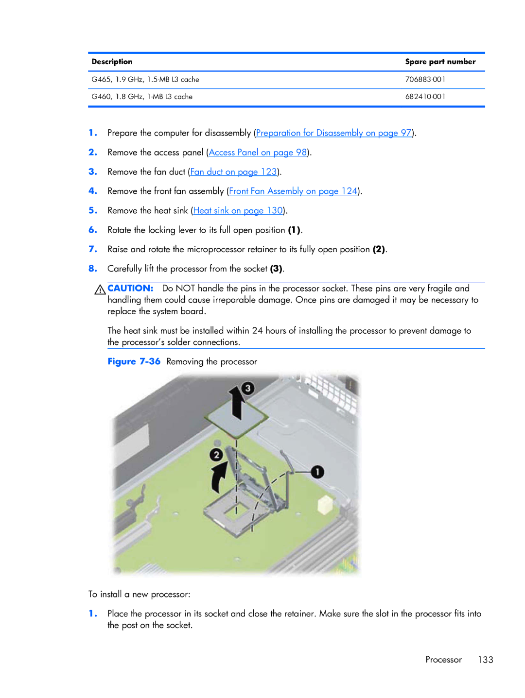
6.Rotate the locking lever to its full open position (1).
7.Raise and rotate the microprocessor retainer to its fully open position (2).
8.Carefully lift the processor from the socket (3).
CAUTION: Do NOT handle the pins in the processor socket. These pins are very fragile and handling them could cause irreparable damage. Once pins are damaged it may be necessary to replace the system board.
The heat sink must be installed within 24 hours of installing the processor to prevent damage to the processor’s solder connections.