MultiProcessor Specification
|
| BSP | AP1 | AP2 | |||
IMCR |
| CPU 1 | CPU 2 | CPU 3 | |||
|
|
|
|
|
|
| |
E0 | NMI | INTR | NMI INTR |
| NMI INTR | ||
|
| LOCAL | LOCAL | LOCAL | |||
REG. |
| APIC | APIC | APIC | |||
|
| 1 | 2 |
|
| 3 | |
MARK | LINTIN0 | LINTIN1 | LINTIN0 | LINTIN1 | LINTIN0 | LINTIN1 | |
| |||||||
LINTIN1 |
|
|
|
|
|
|
|
LINTIN0 |
|
|
|
|
|
|
|
RESET |
|
|
|
|
|
|
|
ICC BUS |
|
|
|
|
|
|
|
NMI |
|
|
|
|
|
|
|
|
|
|
| 8259A- | INTR |
|
|
|
|
|
| EQUIVALENT |
|
| |
|
|
|
| PICS |
|
|
|
INTERRUPT INPUTS |
|
|
|
|
|
| I/O |
|
|
|
|
| APIC | ||
SHADED AREAS INDICATE UNUSED CIRCUITS. DOTTED LINE SHOWS INTERRUPT PATH.
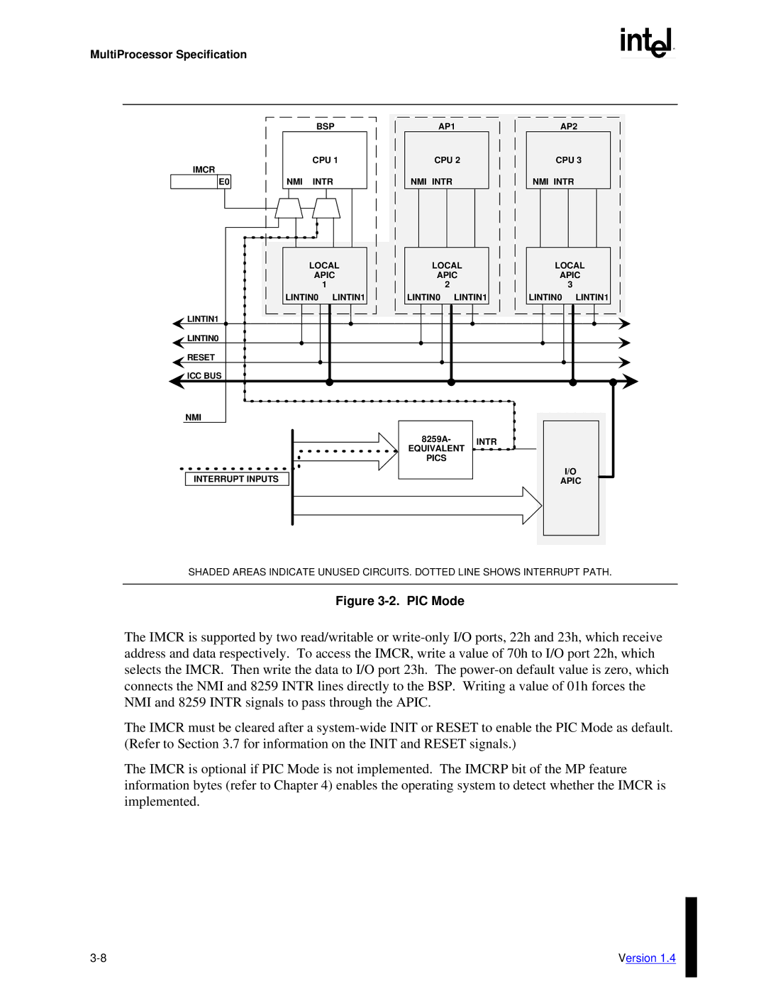
Figure 3-2. PIC Mode
The IMCR is supported by two read/writable or
The IMCR must be cleared after a
The IMCR is optional if PIC Mode is not implemented. The IMCRP bit of the MP feature information bytes (refer to Chapter 4) enables the operating system to detect whether the IMCR is implemented.
Version 1.4 |