Multiple I/O APIC Multiple PCI Bus Systems
Fixed interrupt routing also implies a restriction on software that is implicit but important in the context of systems with more than one I/O APIC. The operating system must program I/O APICs to handle only the interrupts for which the MP configuration table contains corresponding I/O interrupt assignment entries. If the configuration table contains no entry for a given I/O APIC input, that interrupt must be left in the masked state.
D.2 Bus Entries in Systems with More Than One PCI Bus
To accommodate systems with more than one PCI bus within the confines of version 1.1 of this specification, construction of the bus entries on the MP configuration table must be handled in a very particular sequence:
1.Begin with bus entries for the PCI buses. Start at bus zero, using the actual PCI bus number as the bus ID for the bus entry.
2.Add entries for other buses. These entries can use bus ID numbers left vacant by the PCI bus entries.
This sequence implies that bus ID numbers do not have to increase sequentially by increments of one; the requirement is that they must appear in ascending order by bus ID number. This specific interpretation of the information presented in Table
This numbering scheme requires bus entries in the MP configuration table to be sorted appropriately. For example, bus entries should appear in the order PCI (0), EISA (1), and PCI(4) in a system with three buses, two PCI buses numbered 0 and 4, and a single EISA bus numbered as 1.
D.3 I/O Interrupt Assignment Entries for PCI Devices
Section 4.3.4 defines the format of interrupt assignment entries. The example presented there does not, however, completely explain the semantics of the source bus IRQ field for PCI devices.
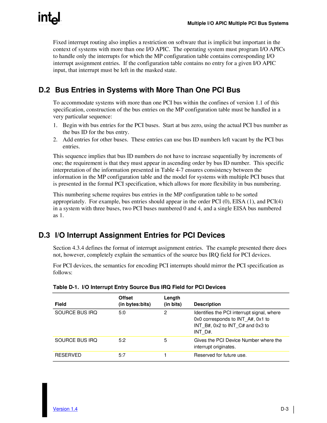
For PCI devices, the semantics for encoding PCI interrupts should mirror the PCI specification as follows:
Table
| Offset | Length |
|
Field | (in bytes:bits) | (in bits) | Description |
|
|
|
|
SOURCE BUS IRQ | 5:0 | 2 | Identifies the PCI interrupt signal, where |
|
|
| 0x0 corresponds to INT_A#, 0x1 to |
|
|
| INT_B#, 0x2 to INT_C# and 0x3 to |
|
|
| INT_D#. |
|
|
|
|
SOURCE BUS IRQ | 5:2 | 5 | Gives the PCI Device Number where the |
|
|
| interrupt originates. |
|
|
|
|
RESERVED | 5:7 | 1 | Reserved for future use. |
|
|
|
|
Version 1.4 |