Page
Important Safety Instructions
Data handling
Handling of the internal hard disk
Iii
RW drive
Printing conventions in this Manual
Table of Contents
Effects
Mixer
Session Drums
Recorder
Vii
Data
Reference
Viii
Appendices
More about drives and files 171
Specifications 174
Various lists 176
Before using the D3200 for the first time
Power on/off
Power-on
Included items
Power-off
Setting the calendar
Press the SYSTEM/MIDI key Click the Control tab
Connection example
Main features Parts and their function Functions LCD screen
Input
Main features
Track digital multi-track recorder
Session Drums
Mixer scene memories, plus Midi control of mixer parameters
CD-R/RW drive for creating backup disk and audio CDs
What is ?
Sophisticated digital editing tools
Intuitive interface designed for ease-of-use
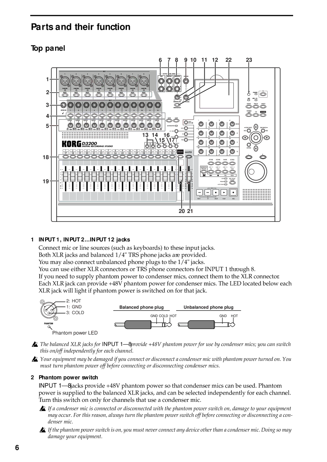
Phantom power switch
Parts and their function
Top panel
Input 1, Input 2...INPUT 12 jacks
60 -40 dBu mic input
13 1-16 key, 17-32 key
14 REC/PLAY key
CH on key
Solo key
Direct keys
Knob Matrix
Scrub key
Mark key
LOOP, TRIGGER, Auto Punch indicators
37 REC/PLAY Mode keys
40 HDD/CD access and Midi indicators
On key, standby indicator
Rear panel
About the CD-R/RW drive
Items and functions in the LCD screen
View
List button
Scroll bar/scroll buttons
Confirmation button
Radio buttons
Selecting and setting parameters
Selecting the page mode
Basic operation
Switching between channels 1-16
Send and equalizer
Editing effects
Selecting a channel
Examples of operation
Connections
Turn the D3200 on
Please note the following items before you begin
Connections
When the demo song ends, press the Stop key
Adjust the mix
Listen to the demo song
Press the Song key to access the Song
Create a new song
Name the song
Create the song
Connect your audio sources to the mixer inputs
Connect mics and instruments to the Input jacks
Confirm the changes
Connect a guitar to the guitar input
Assign the inputs to channels
Press the EQ key to access the EQ/ATT tab Choose a channel
Use the Knob Matrix to adjust the EQ
Adjust the EQ settings of channel
Adding EQ and Effects
Reverb&Delay in the Mono
Applying effects to the input sound
Choose an effect type
Choose an effect program
Setting the recording mode
Recording
Preparations for recording
Normal Select the recording status
Playback
Start recording
Overdubbing
Arm track 2 for recording
Applying effects and EQ to individual channels
Press the EQ key to access the EQ/ATT tab
Applying EQ to each channel/track
Adjusting the pan
Selecting a master effect
Select a track for EQ
Select an effect program
Adjusting the Master Effect 1 Send amount for each track
Checking and adjusting the master effect
Adjust the send amount of each track
Adjust the return form the master effects
Make the desired adjustments, and then press the Stop key
Set the meters to display the post fader levels
Applying an effect to the master bus Final Effect
Choose a final effect
When you‘re done adjusting the master EQ, press the Stop key
Applying EQ to the master bus Master EQ
Adjust the recording level
Recording the master track
Specify a virtual track
Arm the master track for recording
Writing to a CD
Saving your song
Selecting/creating a song
Creating a new song
Using the name library
Renaming a song
Selecting a song
Selecting a song from the song list
Switching the counter display
Switching the information display area
Location
Mixer Effects Session Drums Recorder
Moving to a different location
Using the Mark keys to move
Moving to the location assigned to a mark
Deleting a mark
Session Drums Recorder
Finding a zero-cross point
Finding a precise location Scrub
Press the Scrub key to display the Scrub
Song editing procedure
Song editing
Copying a song
Moving a song
Inputting audio to the mixer
Analog input
Protecting a song
Saving a song
Using the tuner
Inputting the digital audio signal from a MD or DAT
Audio outputs from the mixer
Digital input
Sub input
Mixer settings
Adjusting the volume
Adjusting the pan
EQ Equalizer
Pairing
EQ library Storing and recall- ing EQ settings
Master EQ
Group settings
Monitor settings
Fader groups
CH on groups
Solo settings
Adjusting the cue level
Muting a channel
Storing a mixer setup
Mixer Setup
Click the Yes button or press the panel YES key to save
Storing/recalling a scene
Storing a scene
Recalling a scene
Renaming a scene
Specifying parameters that will be disabled for all scenes
Editing and overwriting a scene
Controlling scenes via Midi
Midi output
Scene automation
Automation
Event automation
When you play back the song, event recording will begin
Playing back the events
Editing events
Turn Automation on Rec
Number of effects and DSP power for each variety of effect
How DSP power is allocated to the effects
Effect type and size
Using insert effects
Using master effects
Using the final effect
Applying insert effects during recording
Editing the effects
Editing the effect parameters
Storing an effect program
For an insert effect
Using external effects
Using a pedal or Midi to control an effect
Controlling effects from an external device
Select the effect that you want to control
Listening to drum patterns
Creating a drum track for an entire song Pattern Map
If you’ve selected Metronome as the group
D3200 contains 756 drum patterns →p.176 Drum Pat- tern List
Recording with Session Drums
Recording additional tracks as you listen to the drum track
Recording patterns on a track
Auditioning the pattern map
Editing a drum kit
Selecting a drum kit
Recording directly to the master track
Editing the sound of a drum kit
Pattern maps
Creating a pattern map
Turn the Click Monitor button off normal display
List, select highlight
Tempo
Editing a pattern map
Tempo track
Song Guide function
Changing the tempo during the song
Tap tempo
Recording
Pattern map tempo
Basic recording
Bounce recording
Switching virtual tracks
Trigger recording
Manual punch-in/out
Using a foot switch for manual punch-in/out
Auto punch-in/out
Loop recording
Creating a master track
Song Locate Mixer Effects Session Drums
Normal playback
Playback
Loop playback
Track editing procedures
Track editing
Playing back an album CD project
Copy a track CopyTrk
Using the clipboard to copy data to another song
Insert blank space InsertTrk
Erase a track EraseTrk
Delete a track DeleteTrk
Deleting track data
Deleting all data of a track
Exchange tracks SwapTrk
Reverse a track ReverseTrk
Optimizing a track OptimizeTrk
Expand/compress a track ExpCmpTrk
Select the expansion/compression mode
Copying to a virtual track
Select the copy-source virtual track
Verify the copy-destination
Exchange two entire tracks SwapWholeTrk
Fade-in/fade-out FadeTrk
Swapping entire tracks
Creating a fade-in
Creating a fade-out
Specify the region where you want to erase punch Noise
Eliminating noise NoiseReduction
Erasing punch noise ErasePunchNoise
Select NoiseReduction
Track At Once
Naming a track
Erase a silent region EraseSilence
Disc At Once
Album CD Project
Write the song
Finalize the disc
Song Locate Mixer Effects Session Drums Recorder
Specify the size of the gaps between each track
Audition the Album CD Project
Check the CD by playing it back on an audio CD player
Ripping a CD
Creating a live CD
Create a master track for this song
Edit the album CD project. Figure E
Backing up
Backing up and restoring
Backing up 1 Song
Execute the backup
When backing up to CD-R/RW
When backing up to the PC drive
Backing up All Data
Restoring backed-up data
Importing an audio file
Audio files
Importing an audio track into the beginning of a track
Importing an audio file into the middle of a track
Exporting an audio file
Exporting an audio file
Using D32XD and D16XD data
Using D3200 data on a different model
Using data from a different model on the D3200
Drive and data compatibility with the Digital Recording
Specifying the drive size
Specifying the PC drive size
Checking the hard disk
Renaming a song drive
Formatting the hard disk
Creating a system recovery
To keep only the audio data that you are actually using
Load system
Drive capacity
PC drive
Checking, renaming, or deleting files
Deleting the Undo data
Sharing event data
Windows users Windows Me/2000 or later
Saving/loading
Macintosh users Mac OS9.0.4 or later
Midi connections
Using Midi
Midi messages used by D3200
Using Midi to control the mixer
Synchronizing two D3200 units
Downloading the operating system
Upgrading the system
ClickPoint Calibration dialog box will appear
Press the panel Enter key
Counter display
Counter
Time Disp Type dialog box
Using the name library
Rename
Editing a name
Meter/Track View
100
2a. CH INPUT/SubMixer
101
2b. PAIR/GROUP
102
2b-1. Channel Pair
2b-2. Fader Group
2c. FADER/PAN/AUTOMATION
103
2c-1. Fader Pan
2c-2. Automation
104
2c-3. Event List
105
2c-4. Edit Scene
2c-5. Scene Filter
106
2c-6. Mixer View
2d. EQ/ATT/PHASE
107
2d-1. EQ/ATT
2d-2. EQ Library
108
2d-3. Phase
2d-4. Master EQ
2e. Send EFF/AUX/REC
109
2f. SOLO/MONITOR
110
2e-5. Rec Send
2f-1. Solo
2g. Mixer Setup
111
2f-2. Monitor
2f-3. Cue Level
112
Ch View
Channel Routing View
3a. Rename
113
Effect Routing
114
Insert EFF
Effects that can be used simultaneously
Techniques for assigning effects
Master EFF1
115
Effect program selection
PAN
116
Master EFF2
Final EFF
117
118
119
Disk Utility
120
HDD, CD
121
122
Edit PC File
Restore
Backup
123
Restore destination
124
Album CD Project
Other data files
125
126
Virtual Track
Master Track
Edit Track
127
CopyTrk
128
Wave dialog box
129
InsertTrk
EraseTrk
DeleteTrk
130
SwapTrk
ReverseTrk
A3.WAVE
131
OptimizeTrk
ExpCmpTrk
A4. Wave
132
CopyWholeTrk
SwapWholeTrk
A3. Virtual
A3. Mode
133
FadeTrk
NormalizeTrk
134
NoiseReduction
ErasePunchNoise
Before execution After execution
Import File
135
EraseSilence
136
Export File
11. CD
137
11a. Album CD
138
11b. Track at once
139
140
11c. CD Player
WAV
141
Undo
Calib
142
143
Drums Track Mixer
144
Pattern Map
145
Mark
Tempo Track
146
Zoom
Rec Mode
LOC 1/IN, … LOC 4/END
Mixer Navigation Tools
147
148
Transport keys
Play/Stop Mode
149
Category Reverb&Delay
150
Category Modulation&Pitch
Category Dynamics&Filter
Category SFX&etc
151
Category Multi
Stereo-type
About the effect algorithms
152
C/R Delay
Stereo/Cross Delay
10 St. Multitap Delay Stereo Multitap Delay
153
Auto Panning Delay
11 St.Modulation Dly Stereo Modulation Delay
154
Stereo Phaser
155
Stereo Flanger
Stereo Vibrato
156
Stereo Tremolo
Stereo Expander
19 St.Pitch Shifter Stereo Pitch Shifter
157
Stereo Limiter
Stereo Gate
Stereo Filter
158
Multiband Limiter
Category SFX&etc SFX/Etc effects
Talking Modulator
Monaural-type
159
Rotary Speaker
Mono Reverb Room
160
161
162
Mono Wah
49 Mn.Ring Modulator Mono Ring Modulator
Tube Pre Amp Sim Tube PreAmp Simulator
163
164
165
Key does not function when pressed
166
Audio files
167
Startup
168
169
170
Drives
171
CD-R/RW drive
PC USB drive
Audio CDs and files
172
Playing an audio CD
Creating an audio CD
173
Loading
WAV-format audio files
Files on the PC USB drive PC files
174
Recorder section
Midi functionality
General
175
Input
Drum Pattern List
176
EQ Library List
Name Library List
Demo Song List
177
178
179
180
181
182
183
Virtual track
Word clock
XLR jack
Index
184
185
CD-RW
REC/PLAY Mode
186
187
USB
188
Midi implementation chart
189
Korg INC