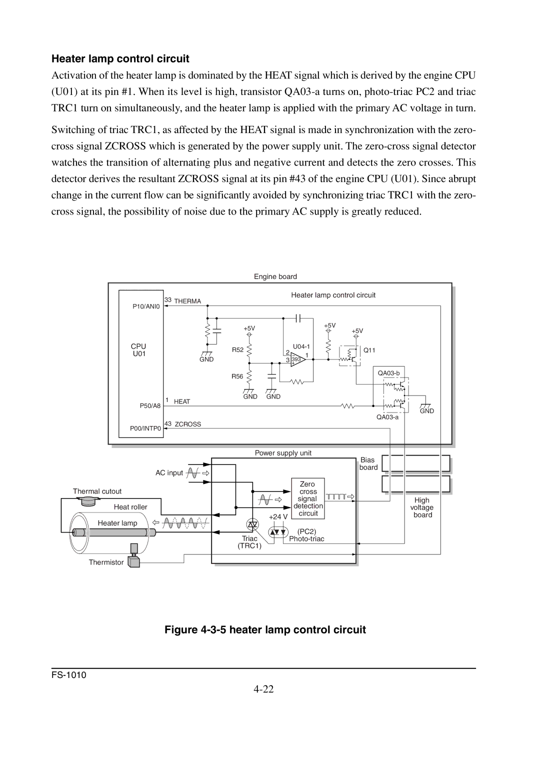
Heater lamp control circuit
Activation of the heater lamp is dominated by the HEAT signal which is derived by the engine CPU (U01) at its pin #1. When its level is high, transistor
Switching of triac TRC1, as affected by the HEAT signal is made in synchronization with the zero- cross signal ZCROSS which is generated by the power supply unit. The
Engine board
33 THERMA |
| Heater lamp control circuit |
| |||
|
|
|
|
| ||
P10/ANI0 |
|
|
|
|
|
|
| +5V |
|
| +5V | +5V |
|
|
|
|
|
| ||
|
|
|
|
|
| |
CPU | R52 | 2 | Q11 |
| ||
U01 | − | 1 |
| |||
GND |
|
| ||||
| 3 | 393 |
|
| ||
|
|
| + |
|
|
|
| R56 |
|
|
|
| |
|
|
|
|
|
| |
1 | GND | GND |
|
|
|
|
HEAT |
|
|
|
|
| |
P50/A8 |
|
|
|
|
| GND |
|
|
|
|
| ||
43 | ZCROSS |
|
|
|
| |
|
|
|
|
| ||
P00/INTP0 |
|
|
|
|
|
|
| Power supply unit | Bias |
| |||
|
|
|
|
|
| |
AC input |
|
|
| board |
| |
|
|
|
|
| ||
Thermal cutout |
|
|
| Zero |
|
|
|
|
| cross |
|
| |
|
|
|
| signal |
| High |
Heat roller |
|
| detection |
| voltage | |
|
| +24 V |
| circuit |
| board |
Heater lamp |
|
|
|
|
| |
|
|
|
|
|
| |
| Triac |
|
| (PC2) |
|
|
|
|
| ||||
| (TRC1) |
|
|
|
|
|
Thermistor |
|
|
|
|
|
|