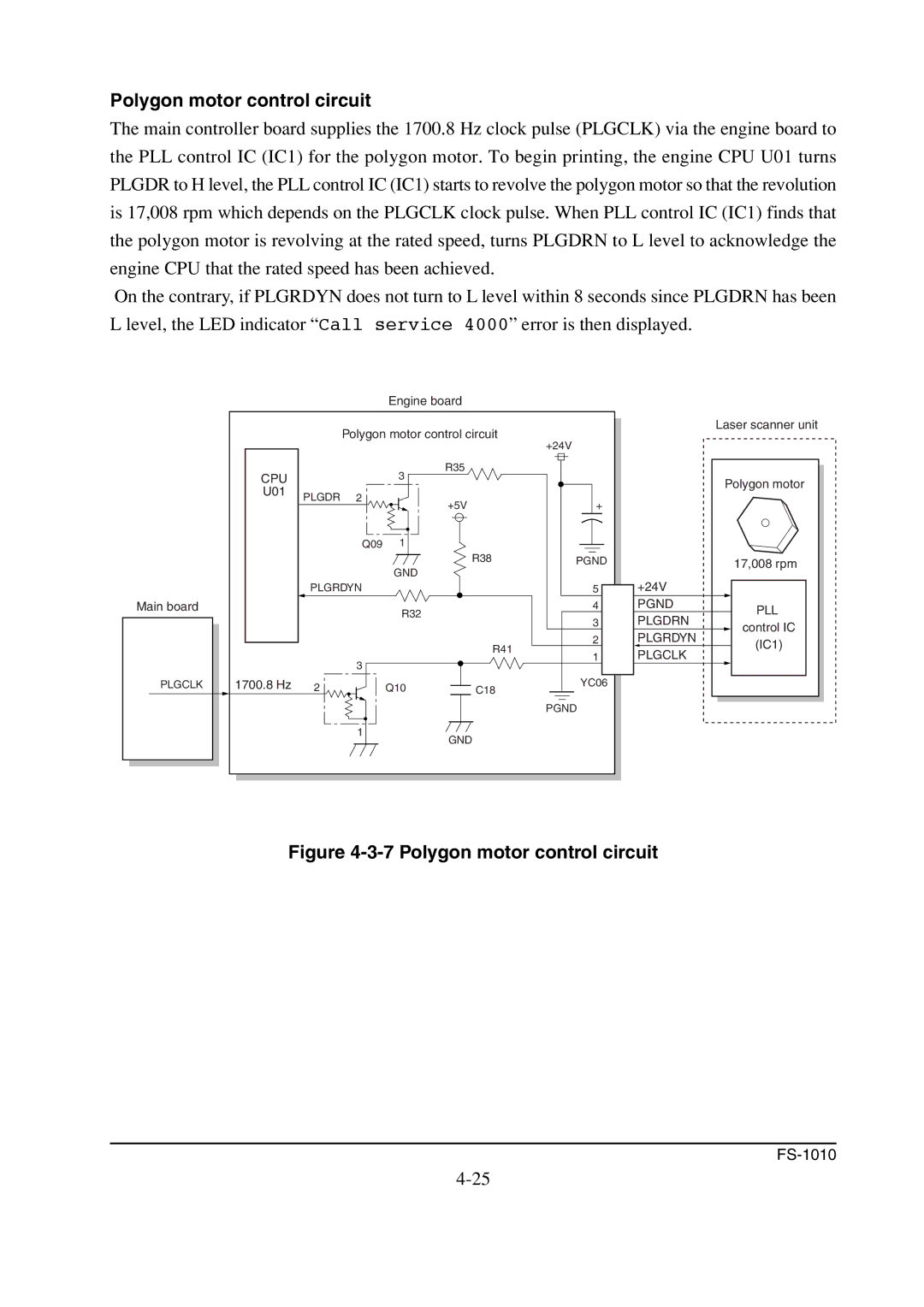
Polygon motor control circuit
The main controller board supplies the 1700.8 Hz clock pulse (PLGCLK) via the engine board to the PLL control IC (IC1) for the polygon motor. To begin printing, the engine CPU U01 turns PLGDR to H level, the PLL control IC (IC1) starts to revolve the polygon motor so that the revolution is 17,008 rpm which depends on the PLGCLK clock pulse. When PLL control IC (IC1) finds that the polygon motor is revolving at the rated speed, turns PLGDRN to L level to acknowledge the engine CPU that the rated speed has been achieved.
On the contrary, if PLGRDYN does not turn to L level within 8 seconds since PLGDRN has been L level, the LED indicator “Call service 4000” error is then displayed.
Main board
PLGCLK
Engine board
|
| Polygon motor control circuit | +24V | ||
|
|
|
|
| |
CPU |
|
| 3 | R35 |
|
|
|
|
| ||
U01 | PLGDR | 2 |
|
|
|
|
| +5V | + | ||
|
|
|
| ||
|
| Q09 | 1 |
|
|
|
|
| GND | R38 | PGND |
|
|
|
|
| |
| PLGRDYN |
|
| 5 | |
|
|
| R32 |
| 4 |
|
|
|
| 3 | |
|
|
|
|
| |
|
|
|
| R41 | 2 |
|
|
|
| 1 | |
|
| 3 |
|
| |
|
|
|
|
| |
1700.8 Hz | 2 |
| Q10 | C18 | YC06 |
|
|
| |||
|
|
|
|
| PGND |
|
| 1 |
| GND |
|
|
|
|
|
| |
| Laser scanner unit | |
| Polygon motor | |
| 17,008 rpm | |
+24V |
| |
PGND | PLL | |
PLGDRN | ||
control IC | ||
PLGRDYN | ||
(IC1) | ||
PLGCLK | ||
|