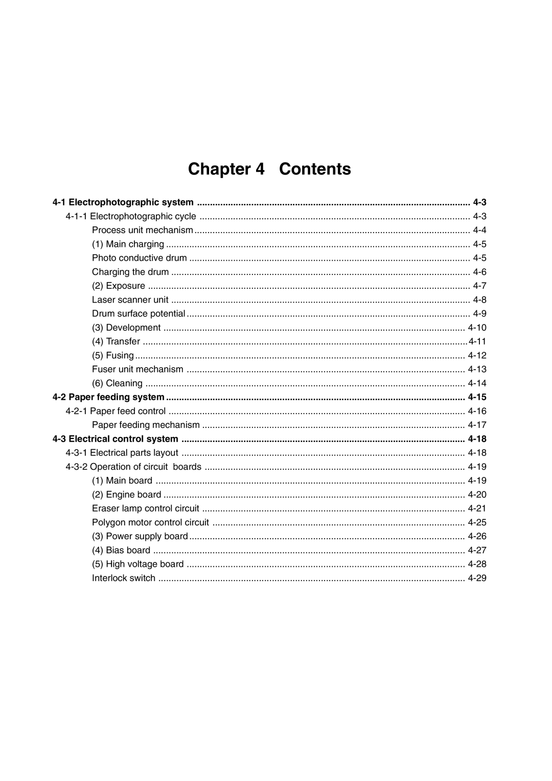
| Chapter 4 | Contents |
Process unit mechanism | ||
(1) | Main charging | |
Photo conductive drum | ||
Charging the drum | ||
(2) | Exposure | |
Laser scanner unit | ||
Drum surface potential | ||
(3) | Development | |
(4) Transfer | ||
(5) | Fusing | |
Fuser unit mechanism | ||
(6) | Cleaning | |
Paper feeding mechanism | ||
(1) | Main board | |
(2) | Engine board | |
Eraser lamp control circuit | ||
Polygon motor control circuit | ||
(3) | Power supply board | |
(4) | Bias board | |
(5) | High voltage board | |
Interlock switch | ||
Page 53
Image 53
