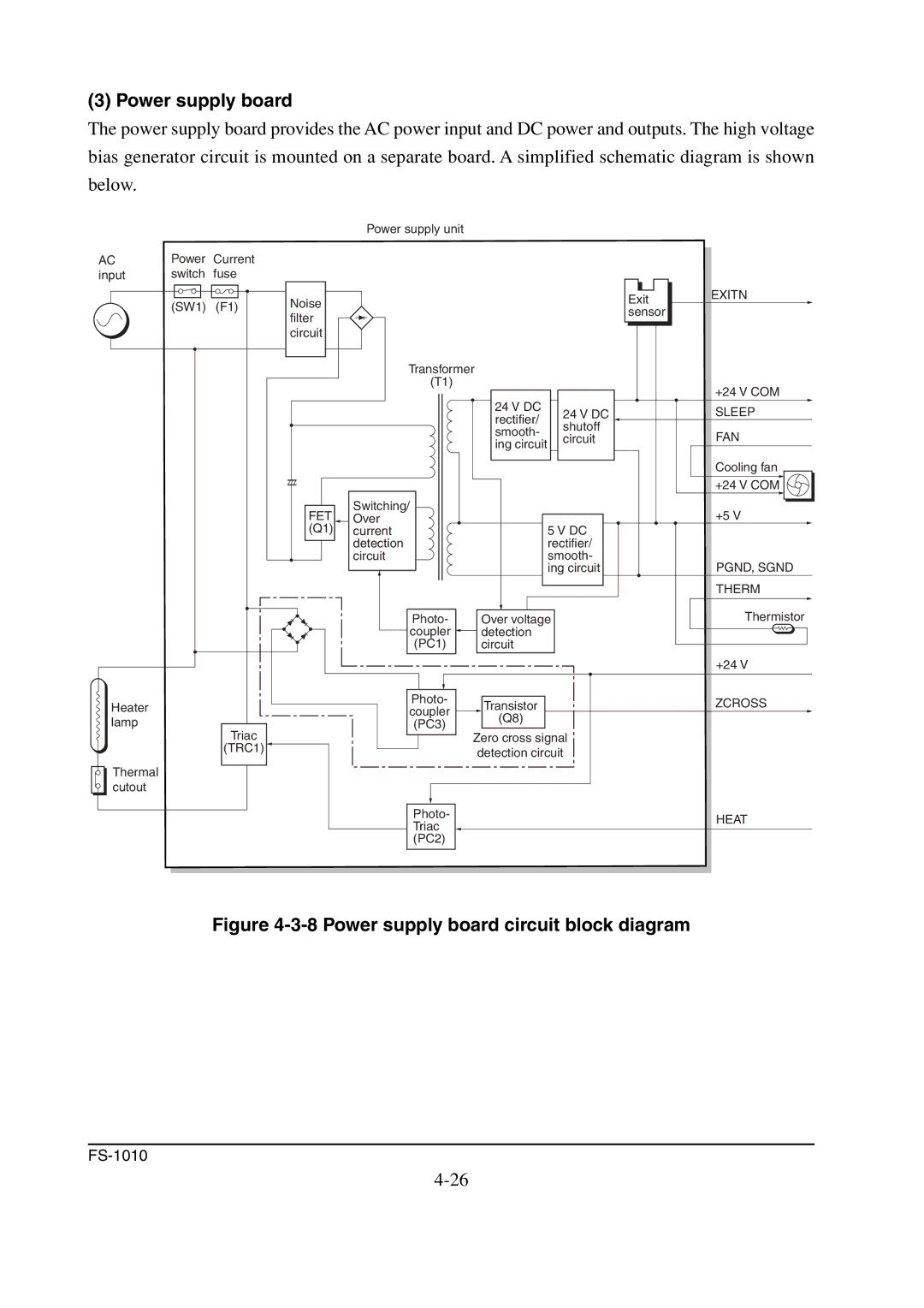
(3) Power supply board
The power supply board provides the AC power input and DC power and outputs. The high voltage bias generator circuit is mounted on a separate board. A simplified schematic diagram is shown below.
Power supply unit
AC | Power | Current |
input | switch | fuse |
| (SW1) | (F1) |
Noise filter circuit
Transformer
(T1)
|
| 24 V DC | 24 V DC |
|
| rectifier/ | |
|
| shutoff | |
|
| smooth- | |
|
| circuit | |
|
| ing circuit | |
|
|
| |
FET | Switching/ |
|
|
Over |
|
| |
(Q1) | current |
| 5 V DC |
| detection |
| rectifier/ |
| circuit |
| smooth- |
|
|
| ing circuit |
| Photo- | Over voltage | |
| coupler | detection |
|
| (PC1) | circuit |
|
Exit | EXITN |
sensor |
|
| +24 V COM |
| SLEEP |
| FAN |
| Cooling fan |
| +24 V COM |
| +5 V |
PGND, SGND |
THERM |
Thermistor |
Heater lamp
Triac
(TRC1) ![]()
Thermal cutout
|
| +24 V | |
Photo- | Transistor | ZCROSS | |
coupler | |||
(Q8) |
| ||
(PC3) |
| ||
Zero cross signal |
| ||
|
| ||
| detection circuit |
|
| Photo- |
| HEAT |
| Triac |
| |
|
|
| |
| (PC2) |
|
|
|
|
|
|