Eraser lamp control circuit
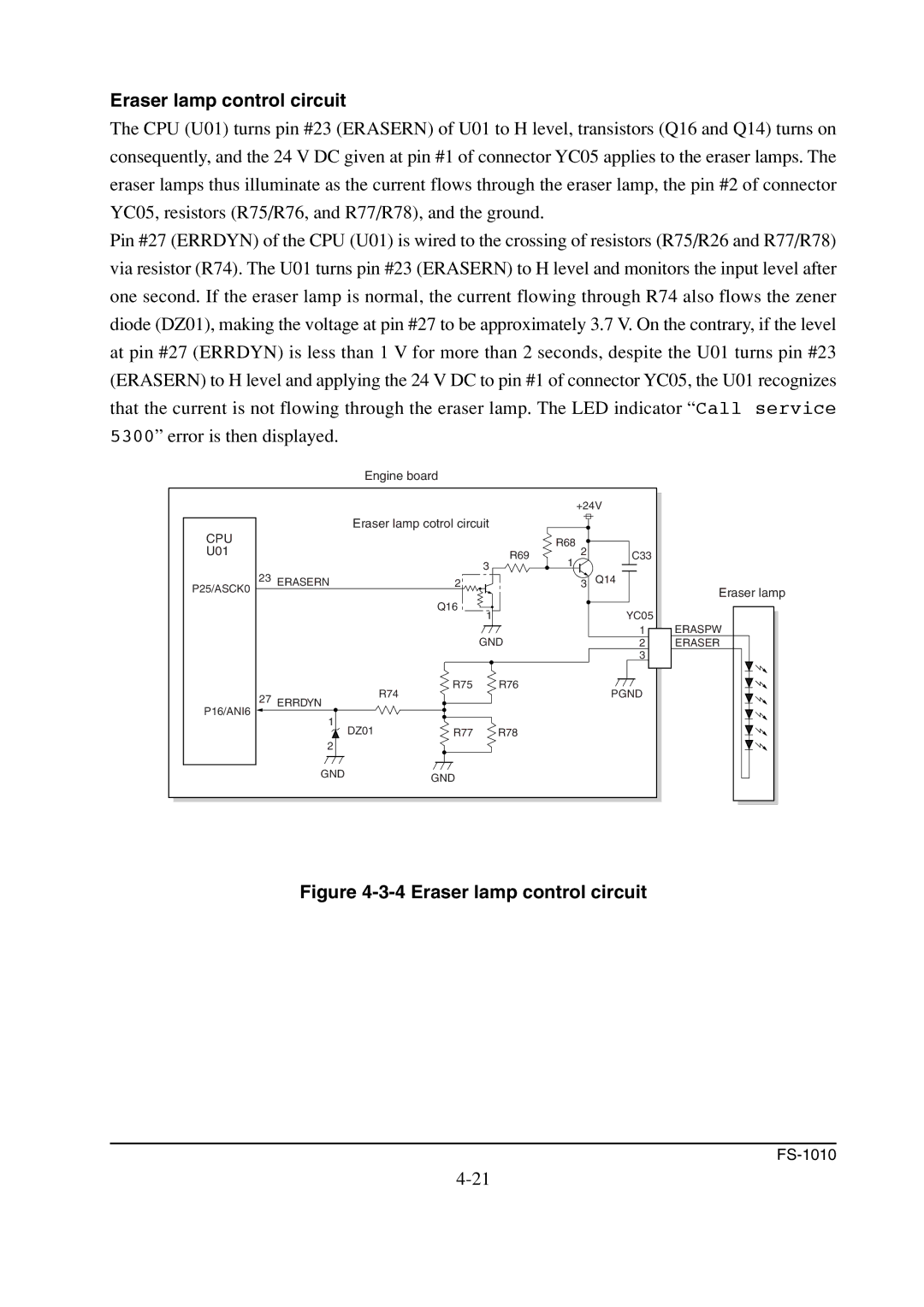
The CPU (U01) turns pin #23 (ERASERN) of U01 to H level, transistors (Q16 and Q14) turns on consequently, and the 24 V DC given at pin #1 of connector YC05 applies to the eraser lamps. The eraser lamps thus illuminate as the current flows through the eraser lamp, the pin #2 of connector YC05, resistors (R75/R76, and R77/R78), and the ground.
Pin #27 (ERRDYN) of the CPU (U01) is wired to the crossing of resistors (R75/R26 and R77/R78) via resistor (R74). The U01 turns pin #23 (ERASERN) to H level and monitors the input level after one second. If the eraser lamp is normal, the current flowing through R74 also flows the zener diode (DZ01), making the voltage at pin #27 to be approximately 3.7 V. On the contrary, if the level at pin #27 (ERRDYN) is less than 1 V for more than 2 seconds, despite the U01 turns pin #23 (ERASERN) to H level and applying the 24 V DC to pin #1 of connector YC05, the U01 recognizes that the current is not flowing through the eraser lamp. The LED indicator “Call service 5300” error is then displayed.
Engine board
|
|
|
| +24V |
| |
| Eraser lamp cotrol circuit |
|
|
| ||
CPU |
|
|
| R68 |
|
|
U01 |
|
| R69 | 2 | C33 |
|
|
|
| 1 |
| ||
|
|
| 3 |
|
| |
23 |
|
|
|
|
| |
ERASERN | 2 |
| 3 | Q14 | Eraser lamp | |
P25/ASCK0 |
|
|
|
|
| |
|
| Q16 | 1 |
| YC05 |
|
|
|
|
|
| ||
|
|
| GND |
| 1 | ERASPW |
|
|
|
| 2 | ERASER | |
|
|
|
|
| 3 |
|
|
| R75 | R76 |
| PGND |
|
27 | ERRDYN | R74 |
|
|
| |
|
|
|
|
| ||
P16/ANI6 | 1 |
|
|
|
|
|
|
|
|
|
|
| |
| DZ01 | R77 | R78 |
|
|
|
| 2 |
|
|
|
|
|
| GND | GND |
|
|
|
|
|
|
|
|
|
| |