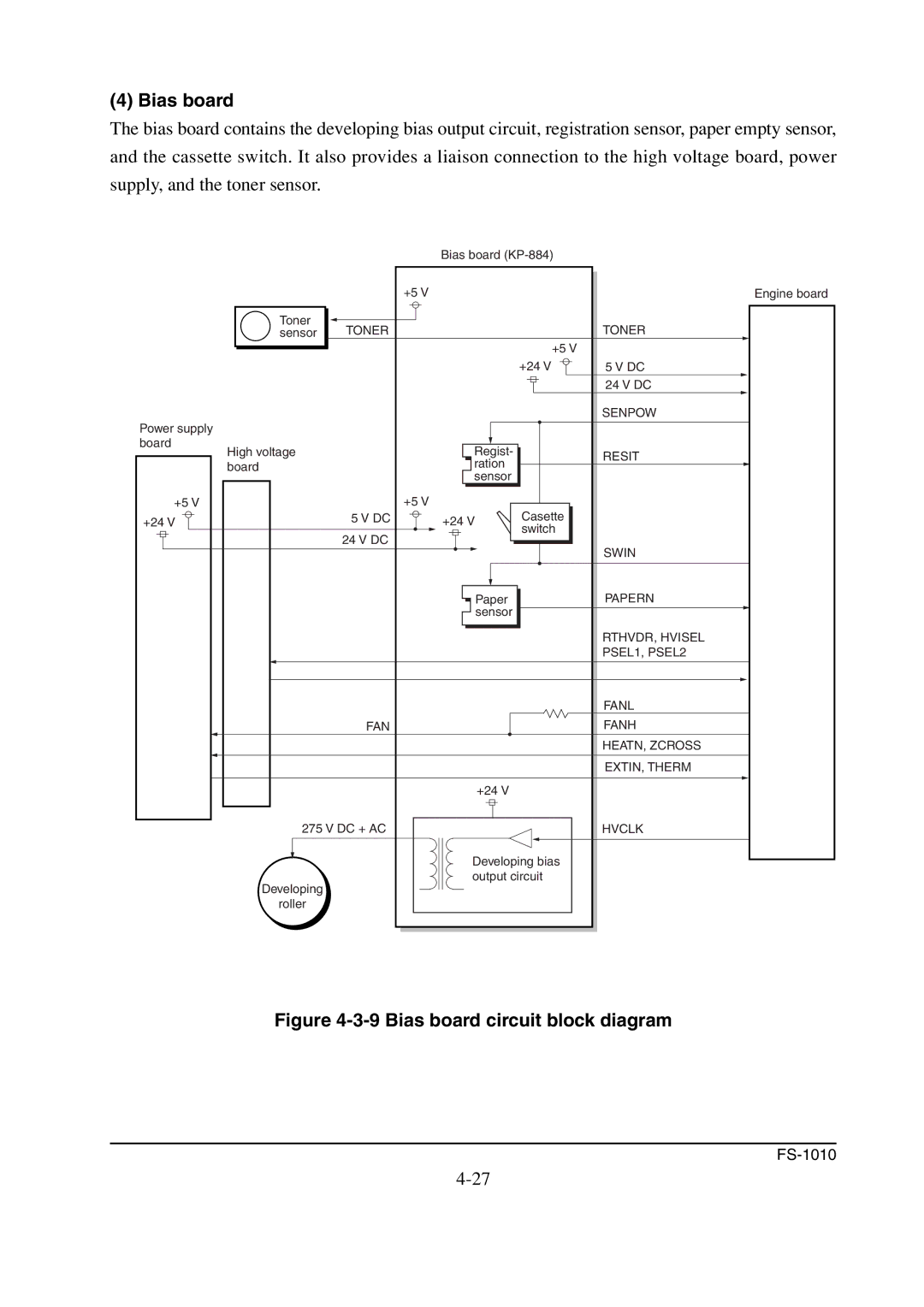
(4) Bias board
The bias board contains the developing bias output circuit, registration sensor, paper empty sensor, and the cassette switch. It also provides a liaison connection to the high voltage board, power supply, and the toner sensor.
|
| Bias board |
| |
| +5 V |
|
| Engine board |
Toner | TONER |
|
| TONER |
sensor |
|
| ||
|
|
| +5 V |
|
|
|
| +24 V | 5 V DC |
|
|
|
| 24 V DC |
|
|
|
| SENPOW |
Power supply |
|
|
|
|
board |
| Regist- |
|
|
High voltage |
|
| RESIT | |
board |
| ration |
| |
|
|
| ||
|
| sensor |
|
|
+5 V | +5 V |
| Casette |
|
+24 V | 5 V DC | +24 V |
| |
| 24 V DC |
| switch |
|
|
|
| SWIN | |
|
|
|
| |
|
| Paper |
| PAPERN |
|
| sensor |
|
|
|
|
|
| RTHVDR, HVISEL |
|
|
|
| PSEL1, PSEL2 |
|
|
|
| FANL |
| FAN |
|
| FANH |
|
|
|
| HEATN, ZCROSS |
|
|
|
| EXTIN, THERM |
|
| +24 V |
|
|
275 V DC + AC |
|
| HVCLK | |
|
| Developing bias |
| |
Developing |
| output circuit |
| |
|
|
|
| |
roller |
|
|
|
|