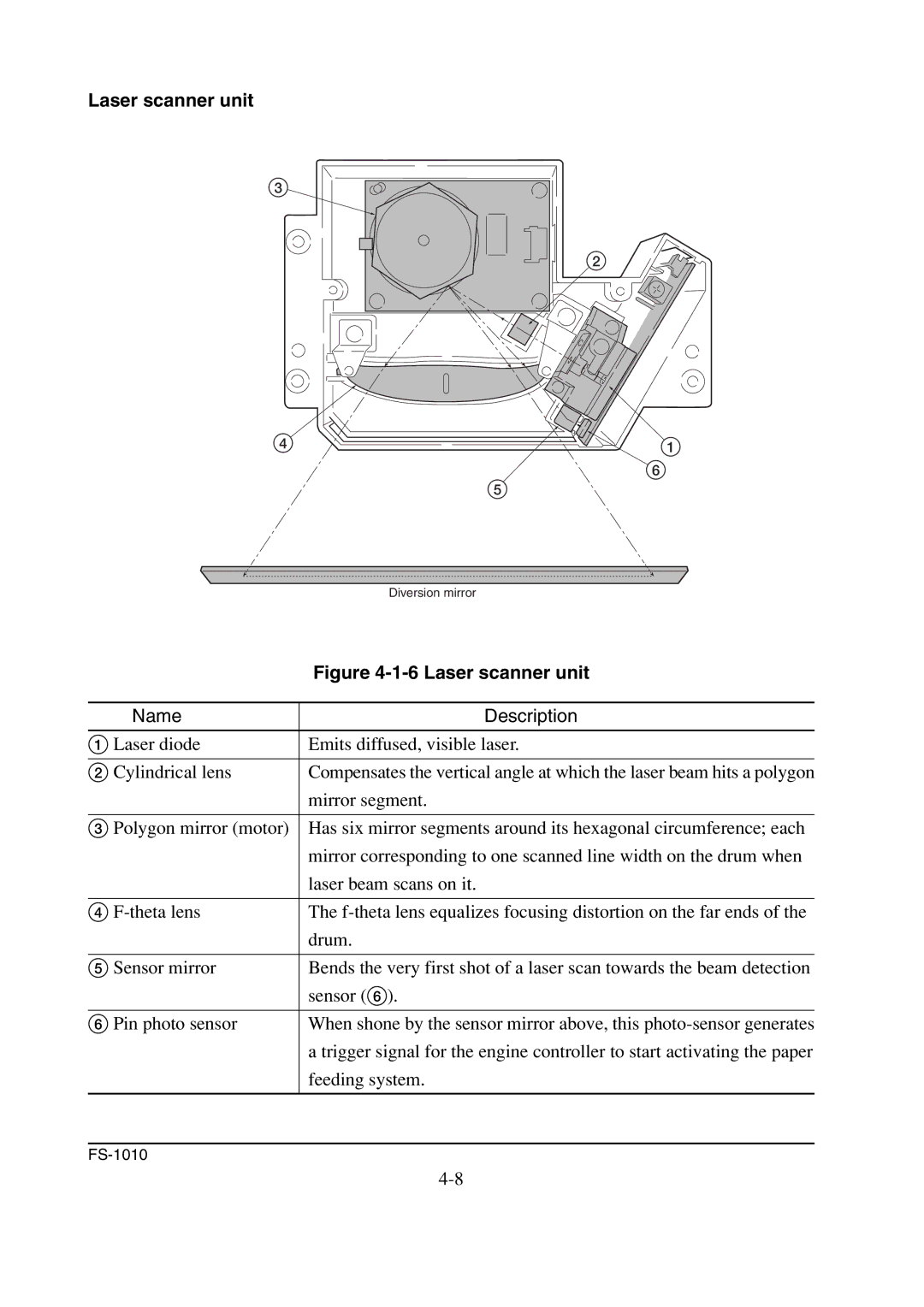
Laser scanner unit
3
2 |
4 ![]() 1
1
6
5
Diversion mirror
| Figure |
|
|
Name | Description |
|
|
1 Laser diode | Emits diffused, visible laser. |
|
|
2 Cylindrical lens | Compensates the vertical angle at which the laser beam hits a polygon |
| mirror segment. |
|
|
3 Polygon mirror (motor) | Has six mirror segments around its hexagonal circumference; each |
| mirror corresponding to one scanned line width on the drum when |
| laser beam scans on it. |
|
|
4 | The |
| drum. |
|
|
5 Sensor mirror | Bends the very first shot of a laser scan towards the beam detection |
| sensor (6). |
|
|
6 Pin photo sensor | When shone by the sensor mirror above, this |
| a trigger signal for the engine controller to start activating the paper |
| feeding system. |
|
|