INSTALLATION
Return to Section TOC
OUTPUT CONNECTIONS
ELECTRODE AND WORK CABLES
Use the shortest possible cable lengths. See Table A.1 for recommended cable sizes based on length.
TABLE A.1
Cable Sizes for Combined Lengths of Copper
Electrode and Work Cable
| Cable Length | Parallel Cables | Cable Size |
| ft. (m) |
|
|
|
|
|
|
0 | (0) to 100 (30.4) | 2 | 2/0 ( 70mm2) |
100 | (30.4) to 200 (60.8) | 2 | 3/0 ( 95mm2) |
200 | (60.8) to 250 (76.2) | 2 | 4/0 (120mm2) |
|
|
|
|
2.Connect the electrode cable to the positive terminal marked “+”.
3.Remove the terminal strip access cover panel on the lower case front. Refer to Figure A.3 for the location.
4.Work Sense lead #21 from the 14 Pin
Note: This is how the
5.Replace the terminal strip access cover panel.
Return to Section TOC
Section TOC
Return to Master TOC
Return to Master TOC
Master TOC
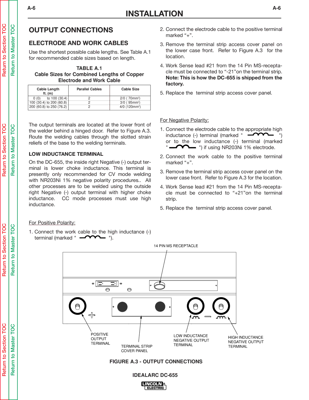
The output terminals are located at the lower front of the welder behind a hinged door. Refer to Figure A.3. Route the welding cables through the slotted strain reliefs of the base to the welding terminals.
LOW INDUCTANCE TERMINAL
On the
For Positive Polarity:
1.Connect the work cable to the high inductance
terminal (marked " ![]()
![]() ").
").
For Negative Polarity:
1.Connect the electrode cable to the appropriate high
inductance ![]()
![]() ")
")
or to | the low inductance |
" | ") if using NR203Ni 1% electrode. |
2.Connect the work cable to the positive terminal marked “+”.
3.Remove the terminal strip access cover panel on the lower case front. Refer to Figure A.3 for the location.
4.Work Sense lead #21 from the 14 Pin
5.Replace the terminal strip access cover panel.
14 PIN MS RECEPTACLE
POSITIVE | LOW INDUCTANCE | HIGH INDUCTANCE | |
OUTPUT | |||
NEGATIVE OUTPUT | |||
NEGATIVE OUTPUT | |||
TERMINAL | |||
TERMINAL | |||
| |||
TERMINAL STRIP | TERMINAL | ||
| |||
COVER PANEL |
|
|