TOC
TOC
ELECTRICAL DIAGRAMS | ||
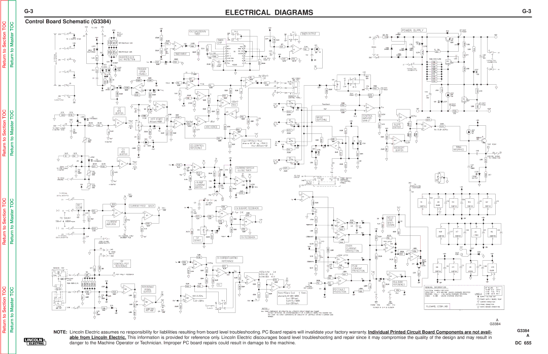
Control Board Schematic (G3384) |
|
|
Return to Section
Return to Section TOC
Return to Master
Return to Master TOC
315
OPTIONALTO | DIGITAL METER PCB |
317
TO (+)
OUTPUT STUD
SHORTED SCR
A.C. PROTECTION
TRIGGER
OPEN
ENABLE
CC
VFB
BUFFER
HOT START
CV
VFB
BUFFER
IDLE SHUTDOWN
TIMER
TIMER
CHIP
TIMER INPUT
Vco
ARC FORCE |
CCCONTROL REFERENCE
TIMER OUTPUT
MODE | CONTROL | |
AMPLIFIER | ||
SWITCHING | ||
GAIN=27 | ||
|
POWER SUPPLY |
| |
317 |
| |
TO |
| |
THERMAL FAN/ |
| |
SNUBBER PCB |
| |
SLOPE |
| |
BUFFER |
| |
INTERCEPT | FIRING | |
INTERFACE | ||
BUFFER | ||
|
315
TO
THERMAL FAN/ SNUBBER PCB
318
Return to Section TOC
TOC
Return to Master TOC
TOC
TO OPTIONAL
DIGITAL METER PCB
201
REF
COM
201
202
202
TO OPTIONAL
DIGITAL METER PCB
CURRENT FEED BACK
CURRENT
AMPLIFIER
CONTROL POT REFERENCE
REFERENCE
SIGNAL
BUFFER
>15 AMP CURRENT SWITCH
CVI
START
CURRENT SWITCH 0.5 SEC TIMER
CV SUBARC FEEDBACK
CV FEEDBACK
CV CURRENT LIMITING
REFERENCE
OVER
CURRENT
PROTECTION
PEAK
CURRENT
PROTECTION
POT FAULT
PROTECTION
TO |
HOLD |
LOW |
SHUT- |
DOWN |
IDLE ZERO |
REFERENCE |
Return to Section
Return to Master
FIRING PCB
A
G3384
NOTE: Lincoln Electric assumes no responsibility for liablilities resulting from board level troubleshooting. PC Board repairs will invalidate your factory warranty. Individual Printed Circuit Board Components are not avail- | G3384 |
able from Lincoln Electric. This information is provided for reference only. Lincoln Electric discourages board level troubleshooting and repair since it may compromise the quality of the design and may result in | A |
| |
danger to the Machine Operator or Technician. Improper PC board repairs could result in damage to the machine. | DC 655 |