to Section TOC
to Master TOC
| |||
|
| ACCESSORIES | |
| The | AUTOMATIC WIRE FEEDERS | |
| the following Lincoln Wire feeders: | CONNECTING THE | |
|
|
| |
|
| IDEALARC | |
| • | • | 1. Set Idealarc |
|
| ||
OFF (0) position.
Return
TOC
Return
TOC
• | • | ||
• | • | ||
• | • | ||
• | • |
AUTOMATIC WIRE FEEDERS*
• | • |
| |
• | • |
2.Disconnect main AC input power to the Idealarc
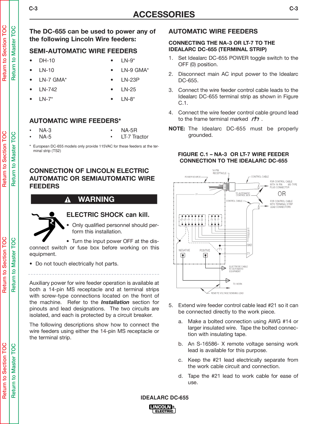
3.Connect the wire feeder control cable leads to the Idealarc
4.Connect the wire feeder control cable ground lead
to the frame terminal marked ![]() .
.
NOTE: The Idealarc
Return to Section
Return to Section TOC
Return to Section TOC
Return to Master
Return to Master TOC
Return to Master TOC
*European
CONNECTION OF LINCOLN ELECTRIC AUTOMATIC OR SEMIAUTOMATIC WIRE FEEDERS
WARNING
ELECTRIC SHOCK can kill.
•Only qualified personnel should per- form this installation.
•Turn the input power OFF at the dis- connect switch or fuse box before working on this equipment.
•Do not touch electrically hot parts.
Auxiliary power for wire feeder operation is available at both a
The following descriptions show how to connect the wire feeders using either the
FIGURE C.1 – NA-3 OR LT-7 WIRE FEEDER CONNECTION TO THE IDEALARC DC-655
| RECEPTACLE |
|
|
POWER SOURCE |
| CONTROL CABLE |
|
|
| FOR CONTROL CABLE | |
|
| WITH 14 PIN | |
|
| PLUG CONNECTOR | |
21 | TO AUTOMATIC | OR |
|
CONTROL BOX |
| ||
|
| ||
| CONTROL CABLE | FOR CONTROL CABLE | |
|
| WITH TERMINAL STRIP | |
|
| LEAD CONNECTORS | |
+21 - 21 41 | 4 | 2 | 31 | 32 | 75 | 76 | 77 |
|
|
|
|
|
|
| 77 |
|
|
|
|
|
|
| 76 |
|
|
|
|
|
|
| 75 |
|
|
|
|
|
|
| 32 |
|
|
|
|
|
|
| 31 |
|
|
|
|
|
|
| 2 |
|
|
|
|
|
|
| 4 |
|
|
|
|
|
|
| GND |
NEGATIVE |
|
|
| POSITIVE |
|
| 21 |
|
|
|
|
|
|
| |
|
|
|
|
|
|
| ELECTRODE CABLE |
|
|
|
|
|
|
| TO AUTOMATIC |
|
|
|
|
|
|
| EQUIPMENT |
|
|
|
|
|
|
| TO WORK |
REMOTE VOLTAGE SENSING LEAD
5.Extend wire feeder control cable lead #21 so it can be connected directly to the work piece.
a.Make a bolted connection using AWG #14 or larger insulated wire. Tape the bolted connec- tion with insulating tape.
b.An
c.Keep the #21 lead electrically separate from the work cable circuit and connection.
d.Tape the #21 lead to work cable for ease of use.
IDEALARC