OPERATION
Return to Section TOC
THERMAL SHUTDOWN
This welder has thermostatic protection from exces- sive duty cycles, overloads, loss of cooling, and high ambient temperature. When the welder is subjected to an overload or loss of cooling, a thermostat will open. This condition will be indicated by the illumination of the yellow Thermostatic Protection Light on the case front (see Figure B.1). The fan will continue to run to cool the power source. No welding is possible until the machine is allowed to cool and the Thermostatic Protection Light goes out.
SHORTED RECTIFIER FAULT PROTECTION
If a short occurs across one of the silicon controlled rectifiers of the
If this input shutdown occurs the input power pilot light remains lit, since the power switch is ON and control power is still present. Welding output or auxil- iary supply output will not be present.
Return to Section TOC
to Section TOC
Return to Master TOC
Return to Master TOC
to Master TOC
OVER CURRENT PROTECTION
SHUTDOWN
Average Current Shutdown
To protect the SCR’s , the
0.3seconds if averaging over 1200 amps (shorter time for higher current). Control PC board LED4, shutdown light, will turn on.
This average current shut down can only be reset by opening the feeder gun trigger, or switching the DC- 655 Output/Remote switch out of the “on” position.
Peak Current Shutdown
To protect the SCRs, the
This peak current shut down can be reset by turning the
REMOTE CONTROL LEADS FAULT PROTECTION SHUTDOWN1
This input shut down is reset by turning the
IDLE SHUTDOWN TIMER
For additional operating economy, the
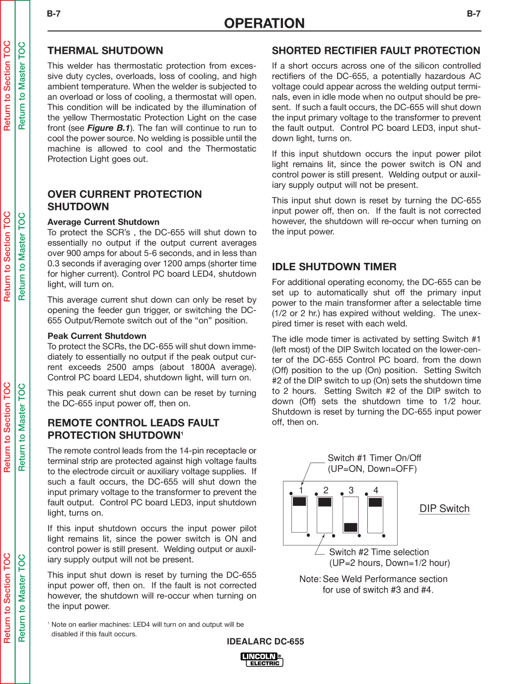
The idle mode timer is activated by setting Switch #1 (left most) of the DIP Switch located on the
Return
to Section TOC
Return
to Master TOC
The remote control leads from the
If this input shutdown occurs the input power pilot light remains lit, since the power switch is ON and control power is still present. Welding output or auxil- iary supply output will not be present.
This input shut down is reset by turning the
Switch #1 Timer On/Off
(UP=ON, Down=OFF)
1 | 2 | 3 | 4 |
DIP Switch
![]() Switch #2 Time selection (UP=2 hours, Down=1/2 hour)
Switch #2 Time selection (UP=2 hours, Down=1/2 hour)
Note: See Weld Performance section for use of switch #3 and #4.
Return
Return
1Note on earlier machines: LED4 will turn on and output will be disabled if this fault occurs.
IDEALARC